Check patentability & draft patents in minutes with Patsnap Eureka AI!

Liquid ejecting head and liquid ejecting apparatus

A technology of liquid ejection head and ejection device, which is applied in the direction of liquid ejection device, ejection device, inking device, etc., and can solve the problems of relative position deviation of multiple head bodies and reduction of printing quality, etc.

Active Publication Date: 2013-09-11
SEIKO EPSON CORP
View PDF9 Cites 0 Cited by
  • Summary
  • Abstract
  • Description
  • Claims
  • Application Information

AI Technical Summary

Problems solved by technology

[0004] However, there is a problem in that the fixing member to which a plurality of head bodies are fixed expands or contracts due to changes in temperature or humidity, and the positioning pins provided on the fixing member and inserted into the positioning holes of the head bodies make the head bodies to move, thereby causing the relative position of multiple head bodies to shift
[0005] Furthermore, there is a problem that, when the relative positional deviation of the head main body is increased, and the length of the nozzle row is implemented by a plurality of head main bodies, the recording medium will be damaged at the junction of the two head main bodies. Streaks will be produced on the

Method used


Image

  • Liquid ejecting head and liquid ejecting apparatus
  • Liquid ejecting head and liquid ejecting apparatus
  • Liquid ejecting head and liquid ejecting apparatus

Examples


Embodiment approach 1

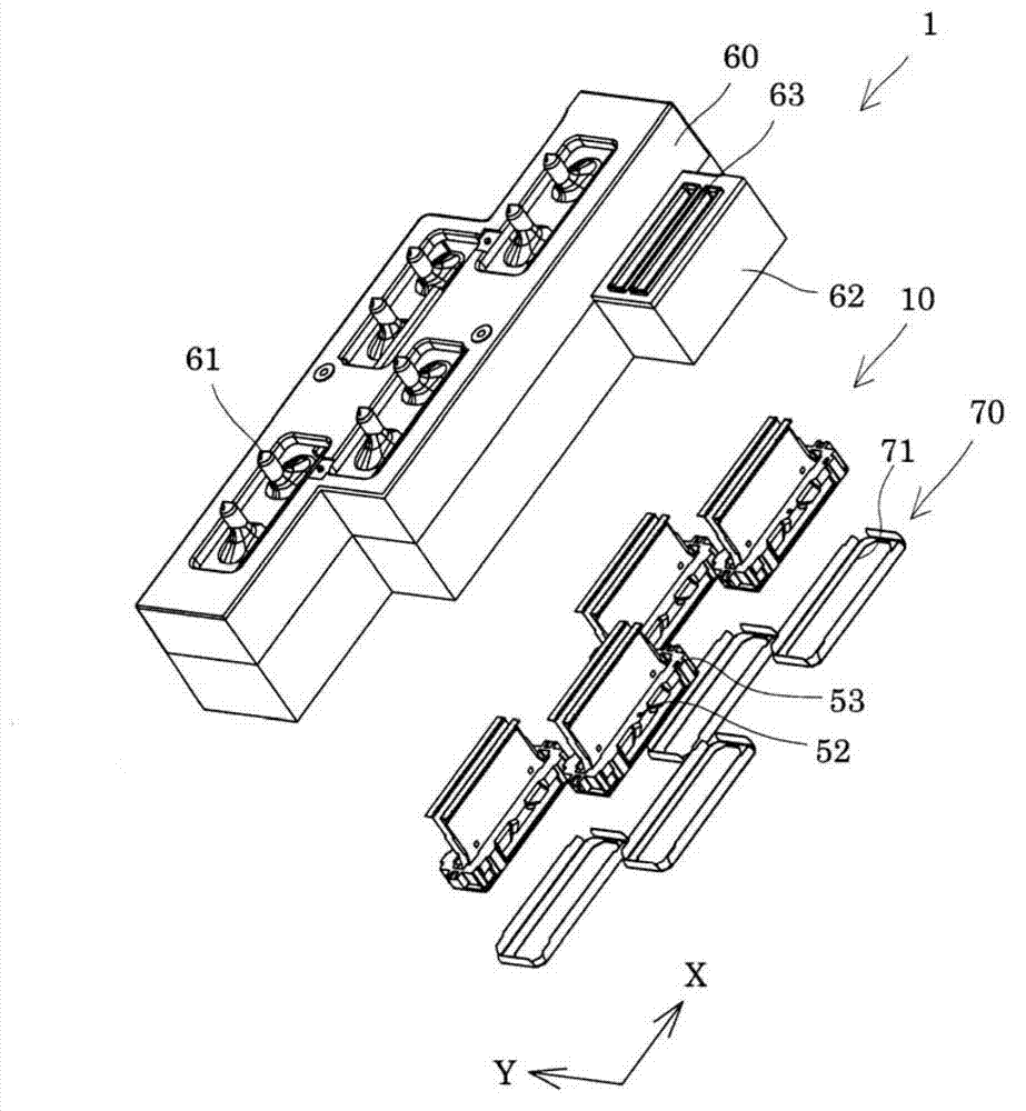
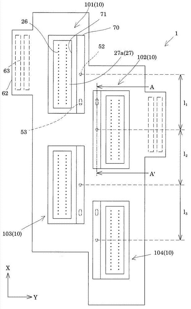
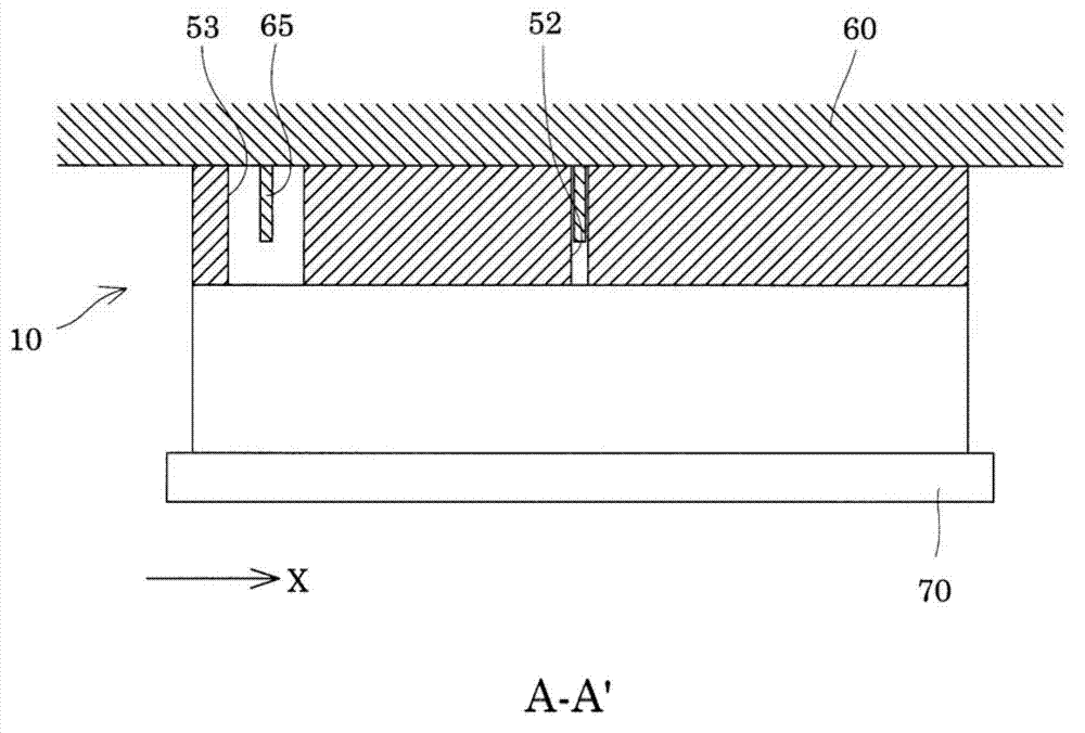
[0028] figure 1 It is an exploded perspective view showing an ink jet recording head as an example of the liquid ejecting head according to Embodiment 1 of the present invention, figure 2 is a plan view of an inkjet recording head viewed from the liquid ejection surface side, image 3 To show the schematic structure of the inkjet recording head, along the figure 2 A cross-sectional view of line A-A' in .

[0029] As shown in the figure, the inkjet recording head 1 includes a plurality of (in this embodiment, four as an example) head main bodies 10 as an example of a liquid ejection head, and a fixing member 60 .

[0030] First, refer to Figure 4 ~ Figure 6 , an example of the structure of the head main body 10 of this embodiment will be described. and, Figure 4 It is an exploded perspective view of the head main body according to Embodiment 1 of the present invention, Figure 5 is a plan view of the head main body viewed from the liquid ejection surface side, Figur...

Embodiment approach 2

[0084] Figure 8 It is a plan view of the liquid ejection surface side of an ink jet recording head as an example of the liquid ejection head according to Embodiment 2 of the present invention. In addition, the same code|symbol is attached|subjected to the same part as Embodiment 1 mentioned above, and duplicative description is abbreviate|omitted.

[0085] Such as Figure 8 As shown, an ink jet recording head 1A as an example of a liquid ejection head according to this embodiment includes a plurality of head main bodies 10A and a fixing member 60 .

[0086] As shown in the figure, in the present embodiment, in the head main body 10A, the first positioning hole 52 is provided on the one end side in the first direction X, and the second positioning hole 53 is provided on the side in the first direction X. the other end side.

[0087]On the fixing member 60, four such head main bodies 10A are fixed. Here, regarding the specific arrangement of the head main bodies 10A in this...


PUM


Abstract

The invention provides a liquid ejecting head and a liquid ejecting apparatus which can inhibit poor records of record mediums caused by changes in temperature or humidity. A liquid ejecting head includes head main bodies (10) having nozzle rows in which nozzle openings configured to eject liquid are arranged; and a fixing member (60) in which rows of the head main bodies (10) arranged in a first direction (X) as an arrangement direction of the nozzle openings are lined in a second direction (Y) perpendicular to the first direction, and the head main bodies (10) are relatively positioned and fixed, the head main bodies (10) are provided with a first positioning hole (52) and a second positioning hole (53) to which positioning pins are inserted, and intervals (11-13) between the first positioning holes (52) of each head main body is shorter than lengths of the nozzle rows of the head main bodies (10).

Description

technical field [0001] The present invention relates to a liquid ejection head and a liquid ejection device that eject liquid from nozzle openings, and more particularly, to an ink jet recording head and an ink jet recording device that eject ink as a liquid. Background technique [0002] A liquid ejecting device typified by an ink jet recording device such as an ink jet printer or a plotter includes a liquid ejecting head capable of ejecting liquid such as ink stored in a cartridge or a tank in the form of droplets. . [0003] For the liquid ejection head used in such a liquid ejection device, when the length (multi-nozzle) or high density of the nozzle opening is implemented as a single unit, the size of the liquid ejection head will increase the size of the finished product. The efficiency is reduced, and the manufacturing cost is high, so it is difficult to realize. Therefore, a unitized liquid ejection head has been proposed in which a plurality of head main bodies ar...

Claims


Application Information

Patent Timeline
Patent Type & Authority Applications(China)
IPC IPC(8): B41J2/01B05B15/68
CPCB05B17/0638B41J2/14233B41J2/155B41J2002/14362B41J2202/20B05B15/68
Inventor 小林宽之
Owner SEIKO EPSON CORP
Features
  • R&D
  • Intellectual Property
  • Life Sciences
  • Materials
  • Tech Scout
  • Unparalleled Data Quality
  • Higher Quality Content
  • 60% Fewer Hallucinations
Learn More