Guide mechanism for positioning light disk module

A guide mechanism and mold technology, applied in the field of guide mechanism, can solve problems such as hidden dangers, pressing molds, balls falling between the movable mold and the fixed mold, etc., to achieve the effect of production safety and solving safety hazards

Active Publication Date: 2013-09-25
KAIPING YINGGUANG ELECTROMECHANICAL TECH
View PDF5 Cites 4 Cited by
  • Summary
  • Abstract
  • Description
  • Claims
  • Application Information

AI Technical Summary

Problems solved by technology

[0003] However, in the process of producing optical discs, the movable mold needs to be opened and closed frequently, so the sleeve frame of the ball sleeve 2' is easy to wear and tear. If the sleeve frame of the ball sleeve 2' is worn and broken, it will be exposed outside the guide sleeve 1'. The balls on the ball sleeve 2' are likely to fall between the movable mold and the fixed mold, causing the die to be pressed, and seriously damaging the mold and its accessories. Compression spring 4', but in the process of long-term frequent mold opening and mold closing,

Method used


Image

  • Guide mechanism for positioning light disk module
  • Guide mechanism for positioning light disk module

Examples


Example Embodiment

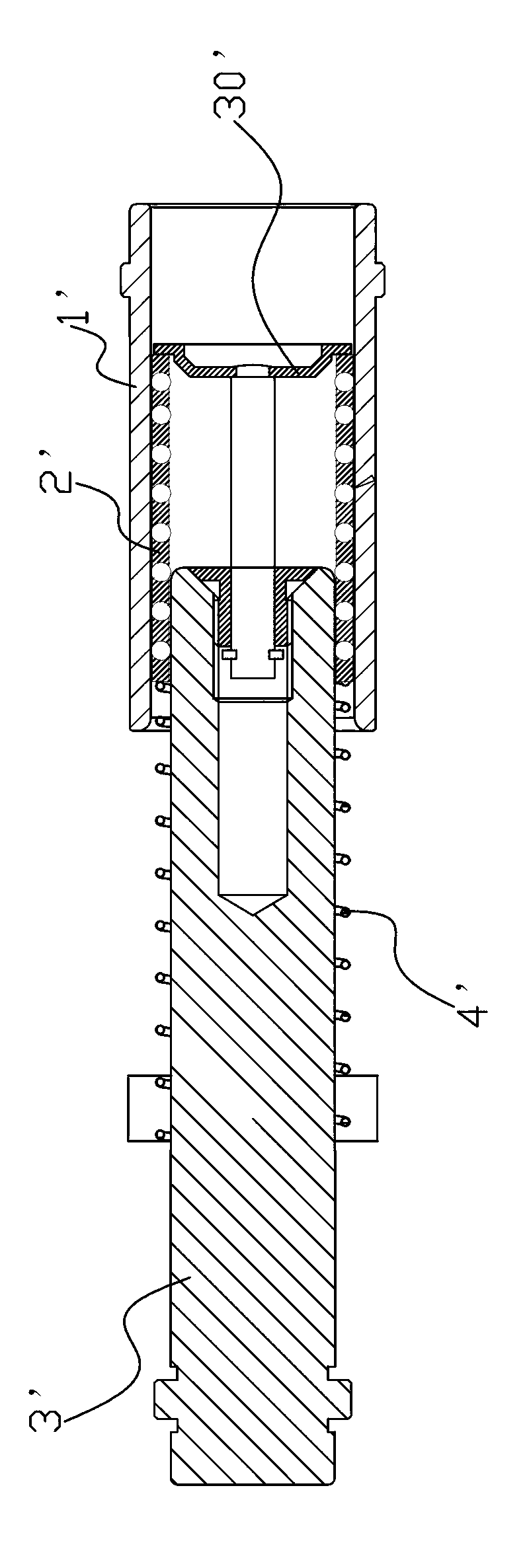
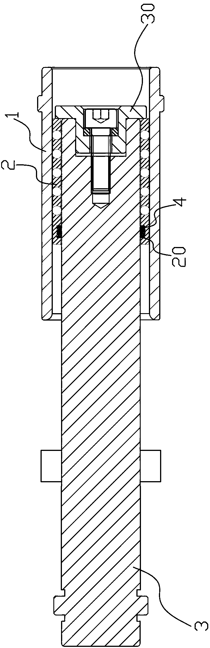
[0014] refer to figure 2 , a guide mechanism for positioning the optical disc mold, including a guide sleeve 1 fixedly installed on the fixed mold, the inner part of the guide sleeve 1 is movably embedded with a ball sleeve 2, and the inner part of the ball sleeve 2 is movably worn and fixed on the The guide post 3 on the movable die, the inside of the ball sleeve 2 is fixedly provided with a wear-resistant ring 4 sleeved on the guide post 3, and the wear-resistant ring 4 and the guide post 3 are separated by a gap. The ball sleeve 2 is fixed on the guide post 3, so the guide post 3 drives the ball sleeve 2 to move toward or away from the fixed die in the guide sleeve 1. When the guide post 3 stops, the ball sleeve 2 It will also stop immediately and will not continue to move forward, so it can be avoided that when the guide post 3 stops, the ball sleeve 2 will continue to move forward along the guide post 3 due to the action of inertia and will be exposed from the guide slee...


PUM


Abstract

The invention discloses a guide mechanism for positioning a light disk module. The guide mechanism comprises a guide sleeve fixedly arranged on a fixed module, wherein the guide sleeve is internally and movably embedded with a ball sleeve; a guide post fixed on a moving module is movably arranged in the ball sleeve in a penetrating manner, the ball sleeve is internally fixedly provided with a wear-resisting ring sleeved on the guide post, and the wear-resisting ring is in interference fit with the guide post. According to the guide mechanism provided by the invention, the wear-resisting sleeve is in interference fit with the guide post through a wear-resisting sleeve sleeved on the guide post in the ball sleeve, and thus, when the moving module opens and moves to a presetting position, and the guide post is immediately stopped; the wear-resisting sleeve is in interference fit with the guide post, and thus, the wear-resisting sleeve is limited by the guide post so as to not unceasingly outward shift, so that the ball sleeve fixedly connected with the wear-resisting sleeve is immediately stopped, and a condition that the ball sleeve can not be exposed outside the guide sleeve is guaranteed.

Description

technical field [0001] The invention relates to a guide mechanism for an optical disc mold. Background technique [0002] As is known to all, the production of optical discs requires a fixed mold that is fixedly installed on a machine tool. The fixed mold is movably mounted with a movable mold that can form a clamping mold or be separated from each other through a positioning mechanism. The above-mentioned positioning mechanism is as follows: figure 1 , the positioning mechanism includes a guide sleeve 1' fixedly installed on the fixed mold, the guide sleeve 1' is movably embedded with a ball sleeve 2', and the inner part of the ball sleeve 2' is movably fitted with a fixed installation on the movable mold. The guide post 3' on the top of the guide post 3' is sleeved with a compression spring 4' for pressing the ball sleeve 2' tightly and preventing it from being exposed from the end of the guide sleeve 1' close to the movable die. One end of the column 3' close to the fixe...

Claims


Application Information

Patent Timeline
IPC IPC(8): B29C33/20
Inventor 张书庭
Owner KAIPING YINGGUANG ELECTROMECHANICAL TECH
Why Eureka
Try Eureka