
Vibration measuring device and method

A vibration measurement and vibration sensing technology, applied in measuring devices, measuring ultrasonic/sonic/infrasonic waves, instruments, etc., can solve the problems of increasing the weight of the diaphragm, poor signal acquisition accuracy, and inability to fully reflect the vibration of the diaphragm. Accurate, Accurately Captured Effects

Active Publication Date: 2013-10-23
LENOVO (BEIJING) LTD
View PDF5 Cites 11 Cited by
  • Summary
  • Abstract
  • Description
  • Claims
  • Application Information

AI Technical Summary

Problems solved by technology

Since the coil is arranged at certain positions on the diaphragm, only the vibration information of a specific position of the diaphragm can be collected, and the vibration of the diaphragm cannot be fully reflected
In addition, the coil is arranged on the diaphragm, which increases the weight of the diaphragm, thereby causing an error in the amplitude of the diaphragm and making the acquisition signal inaccurate; another existing steel ball vibration sensor, by detecting the vibration of the steel ball The vibration generated by the ball, this kind of vibration measurement method also has the phenomenon that the steel ball affects the amplitude of the diaphragm, so there is also the phenomenon of inaccurate signal acquisition
[0004] Through the research on the prior art, the inventor found that: the existing vibration measurement methods all have the problem of poor signal acquisition accuracy

Method used


Image

  • Vibration measuring device and method
  • Vibration measuring device and method
  • Vibration measuring device and method

Examples


Embodiment Construction

[0034] In order to enable those skilled in the art to better understand the technical solutions in the present application, the technical solutions in the embodiments of the present application will be clearly and completely described below in conjunction with the drawings in the embodiments of the present application. Obviously, the described The embodiments are only some of the embodiments of the present application, but not all of them. Based on the embodiments in this application, all other embodiments obtained by persons of ordinary skill in the art without creative efforts shall fall within the scope of protection of this application.

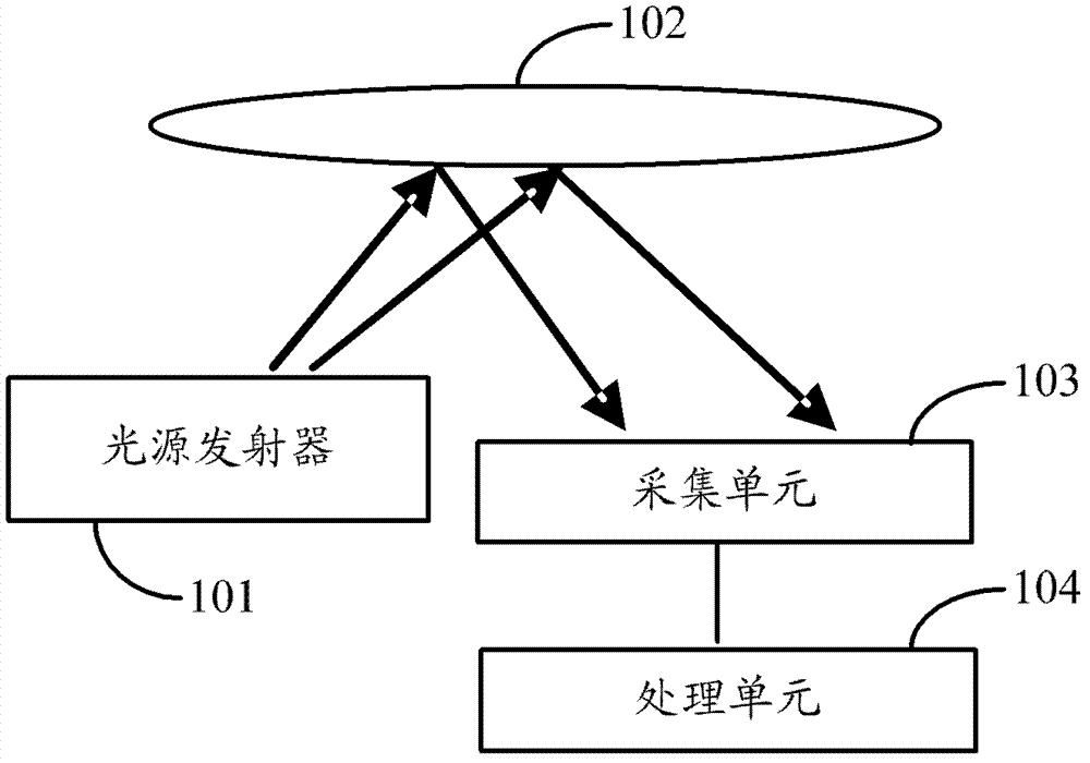
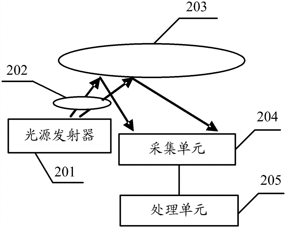
[0035] See figure 1 , shows a schematic structural view of a vibration measuring device, which includes: a light source transmitter 101, a vibration sensing unit 102, an acquisition unit 103 and a processing unit 104, wherein:

[0036] The light source transmitter 101 is configured to emit light beams to the vibration sensing unit 102; ...


PUM


Abstract

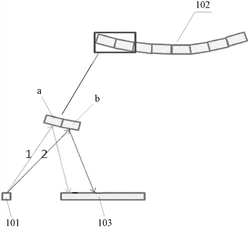
The invention discloses a vibration measuring device and a method. A vibration induction unit is used for inducting a vibration state and emitting light beam emitted by the light source emitter; an acquisition unit is used for collecting the light beam reflected by the vibration induction unit and transforming a collected optical signal to an electrical signal; and an electrical signal corresponding to the reflected light beam is analyzed to obtain a vibration direction and an amplitude size. Specifically, when vibration is received, the vibration induction unit generates corresponding deformation; the reflected light beam generates a corresponding displacement; and the vibration direction and the amplitude size are judged according to displacement changes of the reflected light beam. When the vibration induction unit generates small deformation due to the inducted vibration, the reflected light beam generates comparably big displacement changes; the comparably big displacement changes are realized in the same way that the vibration inducted by the vibration induction unit is amplified; and the accurate acquisition of the vibration is realized and the accuracy of the vibration measuring is improved.

Description

technical field [0001] The present application relates to the technical field of vibration measurement, in particular to a vibration measurement device and method. Background technique [0002] At present, the accuracy of the vibration measurement device has not been accurate enough, which has affected the promotion of the vibration measurement device. [0003] For example, due to the limitation of vibration measurement accuracy, the existing dynamic microphone recording is inaccurate, which limits the speech recognition technology. Specifically, the working principle of the dynamic microphone is as follows. When sound waves vibrate the diaphragm on the dynamic microphone, the coil connected to the diaphragm vibrates with the diaphragm, and the coil vibrates in the magnetic field. The collection current is generated, the size and defense line of the collection current are changing, and the amplitude and frequency are determined by the sound wave. The collection current is a...

Claims


Application Information

Patent Timeline
Patent Type & Authority Applications(China)
IPC IPC(8): G01H9/00
Inventor 阳光
Owner LENOVO (BEIJING) LTD
Learn More