Supercharge Your Innovation With Domain-Expert AI Agents!

Flexible pipe body with buoyancy elements and method of manufacture

A technology of buoyancy element and flexible pipe, applied in the field of flexible pipe body, can solve problems such as lateral deformation of flexible pipe, and achieve the effect of saving cost

Active Publication Date: 2017-09-15
GE OIL & GAS UK LTD
View PDF2 Cites 0 Cited by
  • Summary
  • Abstract
  • Description
  • Claims
  • Application Information

AI Technical Summary

Problems solved by technology

[0012] Another problem associated with riser assemblies is birdcaging, the lateral deformation of the wires of the flexible pipe due to the compressive forces acting on the pipe

Method used


Image

  • Flexible pipe body with buoyancy elements and method of manufacture
  • Flexible pipe body with buoyancy elements and method of manufacture
  • Flexible pipe body with buoyancy elements and method of manufacture

Examples


Embodiment Construction

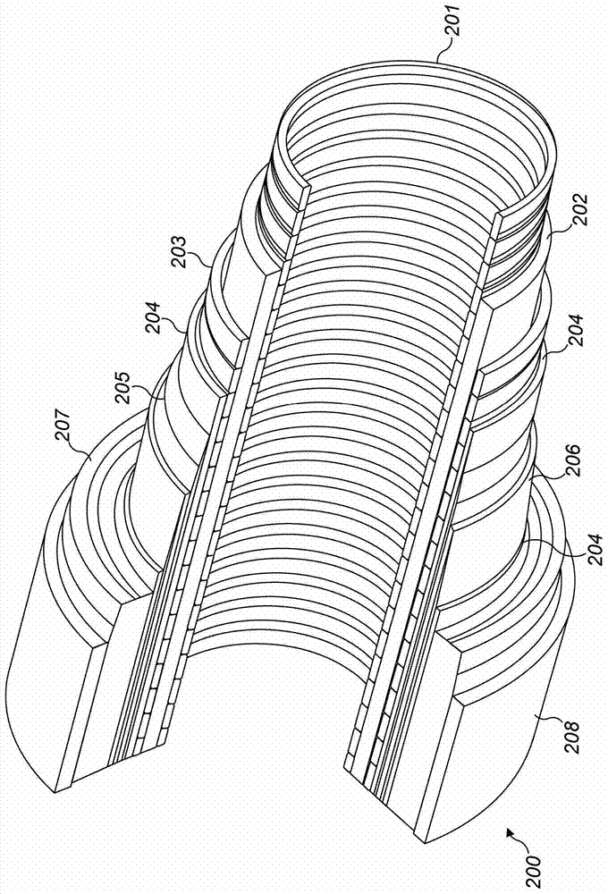
[0033] This article will describe flexible tubing. It should be understood that flexible pipe is an assembly of a portion of a pipe body and one or more end fittings, in each end fitting a respective end of the pipe body terminates. figure 2 It is shown how the combination of layered materials forming the pressure containment conduit constitutes the tubular body 200 . Although in figure 2 A number of specific layers are shown in , but it should be understood that the invention is broadly applicable to coaxial tubular body structures comprising two or more layers of various possible materials. It should be further noted that the layer thicknesses shown are for exemplary purposes only.

[0034] Such as figure 2 As shown, the tubular body includes an optional innermost carcass layer 201 . The carcass provides an interlocking structure that can be used as an innermost layer to fully or partially prevent rupture of the internal pressure sheath 202 due to pipe decompression, ...


PUM


Abstract

The invention discloses a flexible pipe body and a manufacturing method of the flexible pipe body. The flexible pipe body (400) includes an inner fluid-retaining layer (402); an armor layer (404) disposed radially outwardly of the inner fluid-retaining layer; and, including a plurality of discrete elongated buoyancy elements a buoyancy layer (406), the plurality of discrete elongate buoyancy elements disposed radially outwardly of the fluid retaining layer, wound at a helical pitch equal to or greater than 0 degrees and less than about 85 degrees from the longitudinal axis of the flexible pipe body .

Description

technical field [0001] The invention relates to a flexible pipe body including a buoyancy element, and a method for manufacturing the flexible pipe body including the buoyancy element. In particular, but not exclusively, the present invention relates to flexible pipe bodies suitable for use in the oil and gas industry. Background technique [0002] Coiled tubing is traditionally used to transport product fluids such as oil and / or natural gas and / or water from one location to another. Coiled tubing is particularly useful for connecting subsea locations (possibly deep sea, eg, 1000 meters or more) to sea level locations. The inner diameter of the tube may typically be about 0.6 meters. Flexible pipe is generally formed as an assembly of a flexible pipe body and one or more end fittings. The tubing body is generally formed as a combination of layered materials that form the pressure containment conduit. The tube structure allows for large deflections without inducing bendin...

Claims


Application Information

Patent Timeline
Patent Type & Authority Patents(China)
IPC IPC(8): E21B17/01
CPCE21B17/012F16L11/083F16L11/133Y10T29/49826F16L11/00
Inventor 特伦斯·亨利·谢尔德雷克安德鲁·彼得·罗伯茨谈智敏
Owner GE OIL & GAS UK LTD
Features
  • R&D
  • Intellectual Property
  • Life Sciences
  • Materials
  • Tech Scout
  • Unparalleled Data Quality
  • Higher Quality Content
  • 60% Fewer Hallucinations
Learn More