
Stretcher jaw clamping device and mounting method thereof

A fixture device and fixture technology, applied in the directions of transportation and packaging, load hanging components, etc., can solve the problems of increased project cost investment, potential safety hazards, and high labor intensity, so as to reduce the difficulty and labor intensity of operations, and eliminate potential safety hazards. , the effect of improving work efficiency

Active Publication Date: 2013-12-04
CHINA MCC17 GRP
View PDF6 Cites 10 Cited by
  • Summary
  • Abstract
  • Description
  • Claims
  • Application Information

AI Technical Summary

Problems solved by technology

The installation of conventional jaw fixtures is generally carried out manually to the installation position and then adjusted for accuracy. When the jaw fixtures are installed in blocks on C-shaped large boards, due to limited space, the construction operation is greatly affected by the space size, and personnel The labor intensity of lifting and adjusting the position accuracy is very high, and the work efficiency is not high
Moreover, it is easy for people to cause unsafe matters during the process of lifting, handling and adjustment, and there are potential safety hazards. This not only increases the project cost investment, but also increases the risk factors in the installation process, and also affects the construction period of the project installation.

Method used


Image

  • Stretcher jaw clamping device and mounting method thereof
  • Stretcher jaw clamping device and mounting method thereof
  • Stretcher jaw clamping device and mounting method thereof

Examples


Embodiment Construction

[0018] The present invention will be further described below in conjunction with the accompanying drawings.

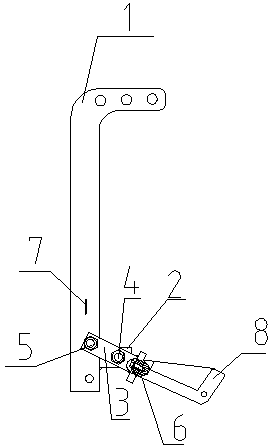
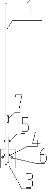
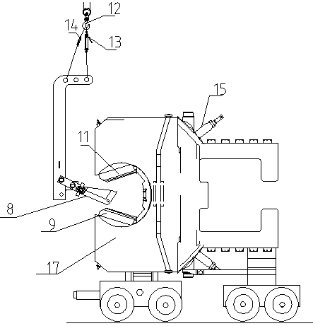
[0019] In the figure, the stretching machine jaw clamp device of the present invention is mainly composed of a boom 1, a support arm 2, a rotating arm 3, a rotating bolt 4, a fixing bolt 5, a connecting bolt 6, a handrail 7, a lower jaw clamp 8, a lower Jaw clamp base 9, upper jaw clamp 10, upper jaw clamp base 11, lifting hook 12, first chain hoist 13, second chain hoist 14, working oil cylinder 15, working wire rope 16, large C-type Block plate 17 forms.

[0020] The device includes a boom 1, a support arm 2, and a rotating arm 3. The upper end of the boom 1 is provided with a hoisting hole, and the lower end is fixedly connected with a support arm 2. The support arm 2 is provided with a rotating bolt 4. The arm 2 is articulated through the rotating bolt 4 and the middle part of the rotating arm 3 , one end of the rotating arm 3 is connected with the boom 1 through ...


PUM


Abstract

The invention discloses a stretcher jaw clamping device and a mounting method thereof. The stretcher jaw clamping device comprises a lifting arm, a support arm and a rotating arm, wherein lifting holes are formed in the upper end of the lifting arm; the lower end of the lifting arm is fixedly connected with the support arm; a rotating bolt is arranged on the support arm; the support arm is hinged to the middle part of the rotating arm through the rotating bolt; one end of the rotating arm is connected with a lower jaw clamp through a connecting bolt; a fixing bolt is mounted at the other end I of the rotating arm; the end I of the rotating arm is connected with the lifting arm. The stretcher jaw clamping device has the advantages as follows: the manufacturing is simple; the mounting is convenient; the operation difficulty and labor intensity of workers in a narrow stretcher are lowered; the input cost is low; the engineering efficiency is improved; lifting equipment is used for lifting, so that the working efficiency is improved, and potential safety hazards when a conventional clamp is carried manually are eliminated.

Description

technical field [0001] The invention relates to metallurgical equipment, in particular to a jaw clamp device and an installation method of a stretching machine. Background technique [0002] With the rapid development of my country's metallurgical and non-ferrous industries, in order to further improve the internal quality of plate profiles, more and more stretching machine configuration and installation projects have appeared in the construction plate production line. There are about 15 combinations of jaw clamps on conventional stretching machines. Each jaw clamp is about 40~60Kg, and they are all installed in the inner arc of the outer opening of the C-shaped large plate of the stretching machine with a diameter of about 1200mm and a semi-circular arc shape, where the installation space is narrow. The installation of conventional jaw fixtures is generally carried out manually to the installation position and then adjusted for accuracy. When the jaw fixtures are installed i...

Claims


Application Information

Patent Timeline
IPC IPC(8): B66C1/10
Inventor 朱道付
Owner CHINA MCC17 GRP
Learn More