Supercharge Your Innovation With Domain-Expert AI Agents!

Proportional pressure reducing valve

A constant-proportion pressure reducing valve and valve body technology, applied in the field of pressure reducing valves, can solve the problems of high noise, unstable pressure reduction, and large vibration, and achieve the effects of reasonable structure, reliable performance, and low vibration and noise.

Active Publication Date: 2015-12-16
淮南华仪泰安机电设备有限公司
View PDF6 Cites 0 Cited by
  • Summary
  • Abstract
  • Description
  • Claims
  • Application Information

AI Technical Summary

Problems solved by technology

The disadvantages of this constant ratio pressure reducing valve are: during work, when the water flow rate is small, it is prone to unstable decompression, large vibration and large noise.

Method used


Image

  • Proportional pressure reducing valve
  • Proportional pressure reducing valve

Examples


Embodiment Construction

[0009] The present invention is further described below with reference to the embodiments and the accompanying drawings.

[0010] see figure 1

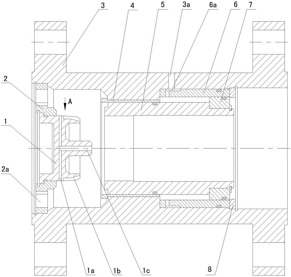
[0011] The proportional pressure reducing valve provided by the present invention has a valve body 3, a movable hollow piston 5 is arranged in the valve body 3, the physical area of ​​the water inlet end of the piston 5 is smaller than that of the water outlet end, and a water inlet end of the valve body 3 is provided with a The water distribution plate 2 is provided with a water inlet hole 2a on the water distribution plate 2. The guide column 1 installed on the water distribution plate 2 is opposite to the piston 5, and the two are in a plug-fit relationship.

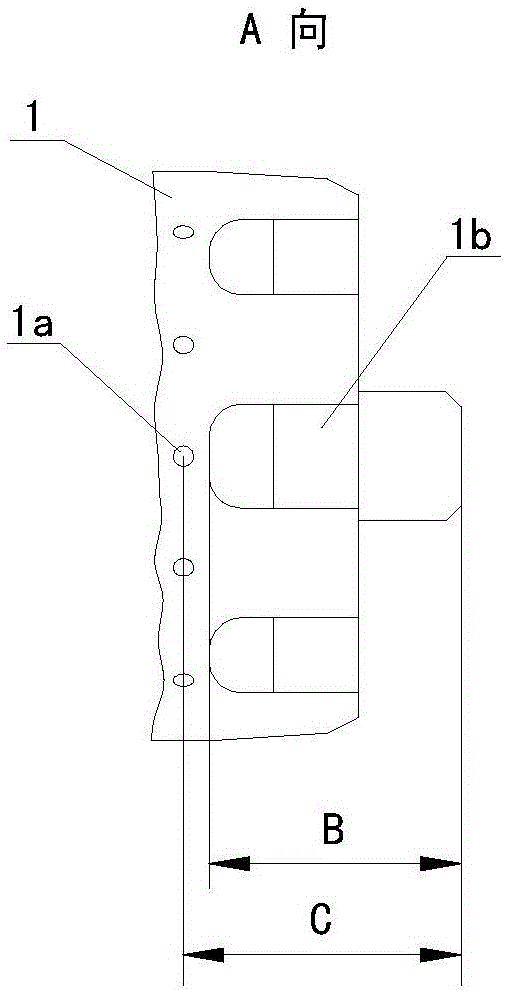
[0012] see figure 1 , figure 2

[0013] There are two or more drainage grooves 1b on the outer surface of the guide column 1. One end of the drainage groove 1b is closed, and the other end penetrates the front end of the guide column 1. A drainage channel 1c and a draina...


PUM


Abstract

The invention discloses a fixed-ratio pressure reduction valve. A piston is arranged in a valve body; a water division plate is arranged at the water feeding end of the valve body; a flow guide column is arranged on the water division plate; more than two drainage slots are formed in the outer side surface of the flow guide column; one end of each drainage slot is closed, and the other end of each drainage slot is communicated with the front end of the flow guide column; a drainage channel and more than one water feeding channel are formed in the flow guide column; an inlet of the water feeding channel is communicated with the outer side surface of the flow guide column, an outlet of the water feeding channel is communicated with the drainage channel; an outlet of the drainage channel is communicated with the front end of the flow guide column. During the use of the fixed-ratio pressure reduction valve, in an initial process that water flow enters from the water division plate and flows out from the valve body, the piston moves towards the flow guide column; when the piston moves to be matched with the flow guide column, the water flow produces pressure loss when passing through the drainage slots; when a product obtained by multiplying the pressure intensity of the water feeding end of the piston and an entity area of the water feeding end is equal to a product obtained by multiplying the pressure intensity of the water discharging end of the piston and an entity area of the water discharging end, the piston stops; the pressure intensity of the water discharging end of the piston is adjusted water pressure. The pressure reduction of the pressure reduction valve cannot be affected by the change of the flow.

Description

technical field [0001] The invention relates to a pressure reducing valve used in a water supply system, in particular to a constant ratio pressure reducing valve. Background technique [0002] The structure of an existing proportional pressure reducing valve used in a water supply system is mainly as follows: a hollow piston is arranged in the valve body, the piston and the valve body are gap-fitted, and the area of ​​the water inlet end of the piston is smaller than the area of ​​the water outlet end. The water inlet end is equipped with a water distribution plate, and the water distribution plate is provided with a water inlet hole. A guide column is connected to the opposite side of the water distribution plate and the piston. The front end of the guide column is provided with a countersunk hole. A number of through holes are opened on the upper part, and the guide column and the piston are in a plug-fit relationship. The disadvantage of this kind of fixed ratio pressur...

Claims


Application Information

Patent Timeline
Patent Type & Authority Patents(China)
IPC IPC(8): F16K17/02
Inventor 王景熙
Owner 淮南华仪泰安机电设备有限公司
Features
  • R&D
  • Intellectual Property
  • Life Sciences
  • Materials
  • Tech Scout
  • Unparalleled Data Quality
  • Higher Quality Content
  • 60% Fewer Hallucinations
Learn More