Rotary grinding machine chuck connection structure

A connection structure and chuck technology, applied in the direction of grinding workpiece supports, etc., can solve the problems of inconvenient clamping and disassembly of parts, low work efficiency, etc., and achieve good locking effect, flexible and convenient use, and prevent parts from being damaged. Effect

Inactive Publication Date: 2013-12-18
张满九
View PDF10 Cites 4 Cited by
  • Summary
  • Abstract
  • Description
  • Claims
  • Application Information

AI Technical Summary

Problems solved by technology

[0007] The present invention overcomes the disadvantages of the existing grinding machine chuck, such as the inconvenience of clamping and dismounting parts, low working efficiency, and the parts are easy to collide with the grinding machine during the process of clamping and dismounting, resulting in damage to the parts, and provides a Rotatable grinding machine chuck connectio

Method used


Image

  • Rotary grinding machine chuck connection structure
  • Rotary grinding machine chuck connection structure
  • Rotary grinding machine chuck connection structure

Examples


Embodiment

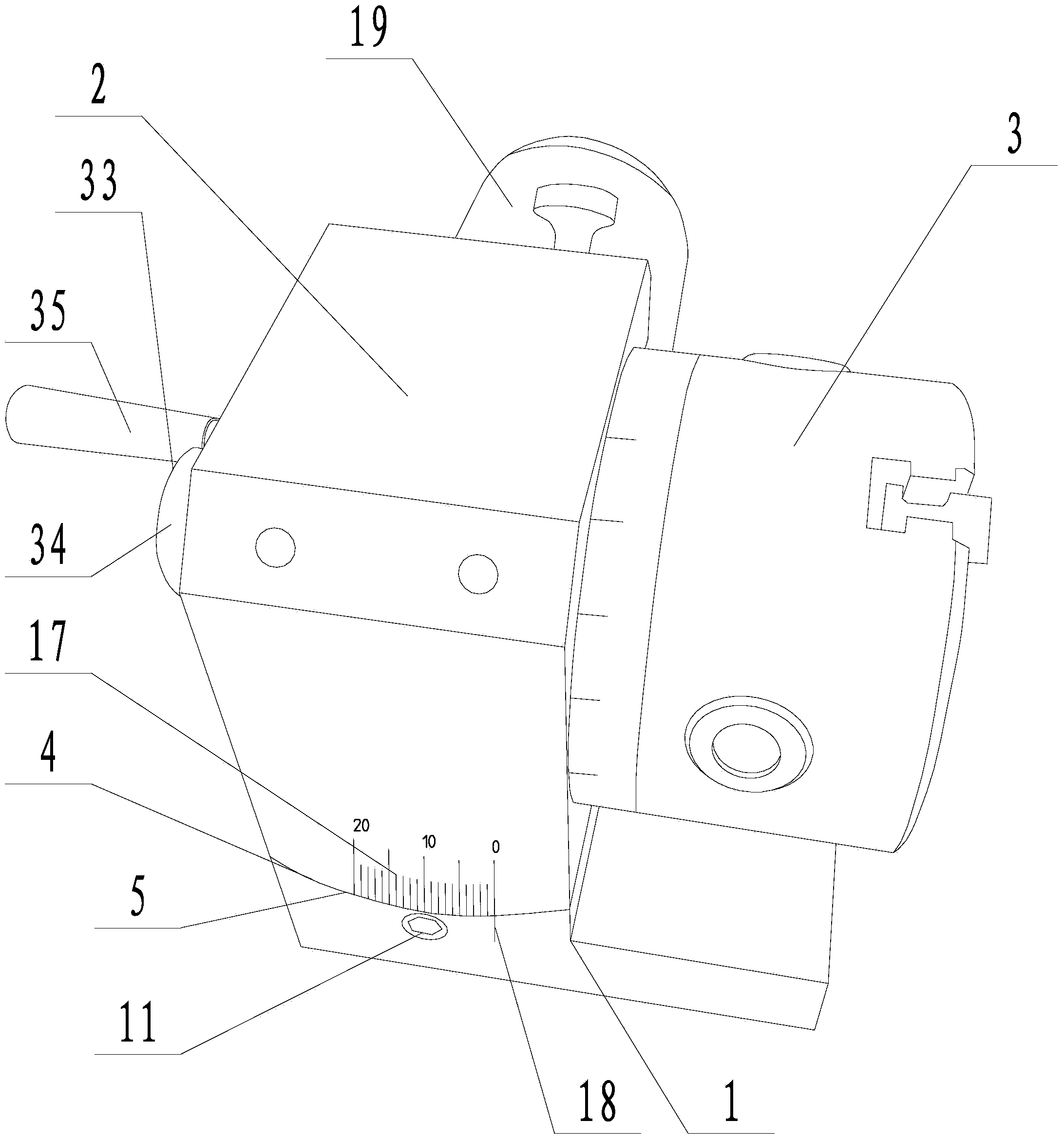
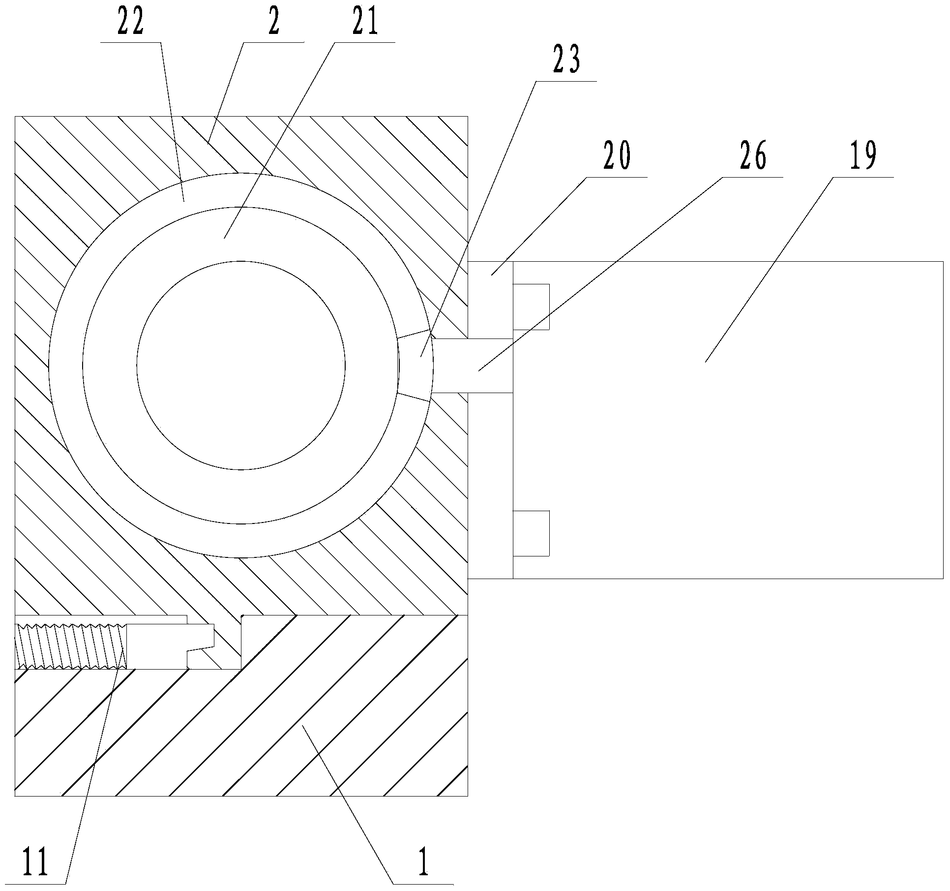
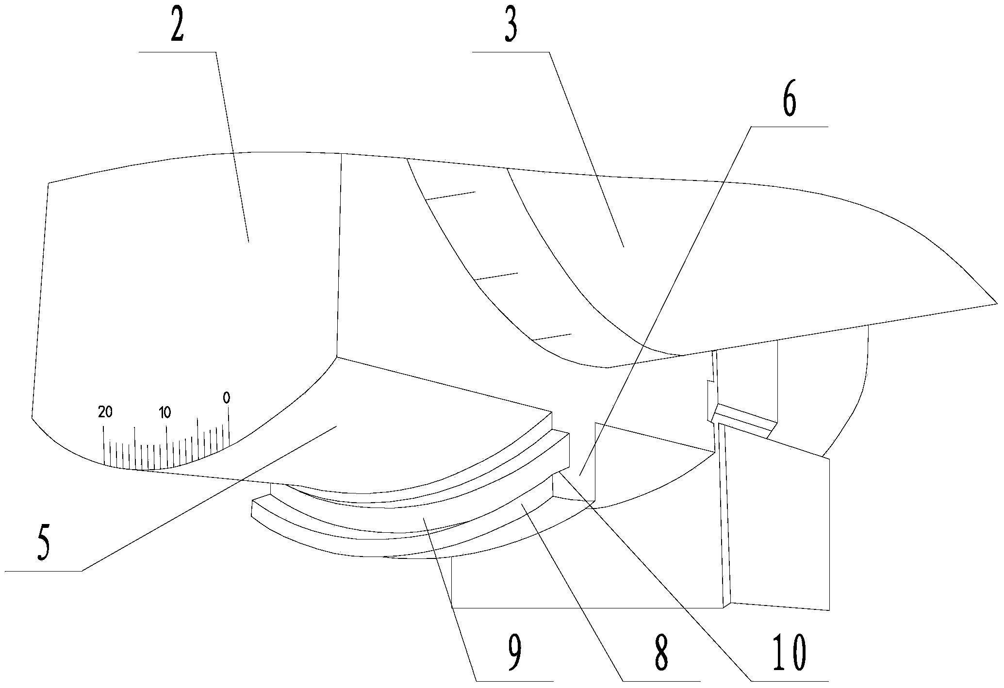
[0028] Embodiment: a kind of rotatable grinding machine chuck connection structure (see attached figure 1 , attached figure 2 ), including a base 1, a chuck seat 2 connected to the base, the chuck body 3 is connected to the right side of the chuck seat, and a concave arc-shaped support surface 4 is provided at the connection position between the base and the chuck seat (see attached Figure 4 ), the arc-shaped support surface is higher than the upper surface of the base, and the arc-shaped support surface has a belt-like structure. The chuck seat is provided with an arc connection surface 5 adapted to the arc support surface (see attached image 3 ), the arc-shaped connection surface is arranged on the lower surface of the chuck seat, and the arc-shaped connection surface supports and fits on the arc-shaped support surface. The arc-shaped connecting surface is provided with an arc-shaped sliding rail 6 along the arc-length direction, and the arc-shaped supporting surface is...


PUM


Abstract

The invention discloses a rotary grinding machine chuck connection structure, and aims at solving the disadvantages that the current grinding machine chuck is inconvenient in clamping and detaching of components and has low working efficiency, and the components in the clamping and detaching processes are likely to impact a grinding machine. The rotary grinding machine chuck connection structure comprises a base and a chuck seat, wherein the chuck seat is connected with a chuck body; the base is provided with an arc supporting surface, the chuck seat is provided with an arc connection surface, the arc connection surface is provided with an arc slide rail, the arc supporting surface is provided with an arc sliding chute, the arc slide rail is connected with the interior of the arc sliding chute, the front side face of the arc slide rail is a limiting face, the limiting face of the slide rail is provided with a limiting slot, and the side face of the lower part of the limiting slot is a locking slope; the base is connected with a limiting column, the front end face of the limiting column is provided with a limiting head, the front end face of the limiting head is propped against the bottom of the limiting slot in a matching manner, a limiting slope is arranged on the limiting head, and the limiting slope is propped against the locking slope in the matching manner, and the front end face of the limiting column below the limiting head is propped against the limiting surface below the limiting slot in the matching manner.

Description

[0001] technical field [0002] The invention relates to a chuck connection device, more specifically, it relates to a conveniently adjustable chuck connection structure for a rotatable grinder. [0003] Background technique [0004] Grinding is an important process step in the processing of mechanical parts. When the existing grinding machine processes the parts, the gripping force provided by the chuck is generally used to block the parts, so as to facilitate the grinding of the parts. After the part has been ground and removed from the chuck, the part is removed by removing the gripping force of the jaws on the chuck. The chuck itself is fixed when clamping and dismounting parts, and there is only one angle for clamping and dismounting of parts, which brings inconvenience to the clamping and dismounting of parts, affects work efficiency, and zero The parts are easy to collide with the grinding machine during the clamping and dismounting process, so that the parts ...

Claims


Application Information

Patent Timeline
IPC IPC(8): B24B41/06
Inventor 张满九
Owner 张满九
Why Eureka
Try Eureka