Check patentability & draft patents in minutes with Patsnap Eureka AI!

construction machinery

A technology of construction machinery and racks, which is applied in the direction of mechanical equipment, earth movers/excavators, fluid pressure actuation devices, etc., can solve the problems of large space occupation and high cost, save resources, improve environmental protection performance, improve Effect of Bridge-to-Charge Ratio Distribution

Inactive Publication Date: 2015-12-23
HUNAN SANY ROAD MACHINERY
View PDF6 Cites 0 Cited by
  • Summary
  • Abstract
  • Description
  • Claims
  • Application Information

AI Technical Summary

Problems solved by technology

[0003] In view of this, the present invention proposes a construction machine to solve the problems of high cost and large occupied space caused by the arrangement of existing fuel tanks, hydraulic oil tanks and / or water tanks

Method used


Image

  • construction machinery

Examples


Embodiment Construction

[0017] It should be noted that, in the case of no conflict, the embodiments of the present invention and the features in the embodiments can be combined with each other. The present invention will be described in detail below with reference to the accompanying drawings and examples.
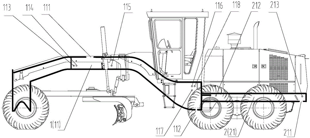
[0018] The basic idea of ​​the present invention is: in order to solve the problems of high cost and large occupied space caused by the arrangement of existing liquid tanks (such as fuel tanks, hydraulic oil tanks and / or water tanks, etc.), the present invention proposes a construction machine, the construction machine The inside of the frame is a cavity structure, and the frame is isolated and closed to form at least one closed section for storing liquids (such as fuel, hydraulic oil or coolant), without the need to separately design liquid tanks (fuel tanks and hydraulic oil tanks) or water tank, etc.) to make the layout of the whole machine more compact and reasonable, and the use of existing ...


PUM


Abstract

The invention discloses engineering machinery which comprises a frame, a drive element, a valve and a radiating device. The frame is provided with a cavity inside and comprises a seal section. The seal section is provided with a liquid inlet, a first liquid outlet and a port for liquid retuning or discharge. The port is connected with the drive element, the valve or the radiating device through a pipeline. The engineering machinery has the advantages that spatial arrangement utilization rate of the whole engineering machinery can be increased, the whole engineering machinery is compact and reasonable in layout, cost lowering is facilitated, efficiency of the whole engineering machinery is increased, resources are saved, environmental friendly performance is increased, and bridge load ratio distribution can be improved effectively.

Description

technical field [0001] The invention relates to the field of engineering machinery, in particular to an engineering machinery with a cavity structure inside the frame. Background technique [0002] The fuel tank, hydraulic oil tank and water tank in the existing construction machinery (such as graders and a hydraulic oil cooling device for construction machinery provided by the patent No. CN201120470603) occupy a large space, affecting the layout of the whole machine, and for For fuel tanks and hydraulic oil tanks, it is generally necessary to design an additional heat dissipation system or increase the heat dissipation capacity of the existing heat dissipation system to ensure that the oil temperature in the fuel tank and hydraulic oil tank is within a reasonable range, resulting in increased costs. In addition, fuel tanks, hydraulic oil tanks, and water tanks are generally located at the rear of the machine, and are far away from the components connected to them, resulting...

Claims


Application Information

Patent Timeline
Patent Type & Authority Patents(China)
IPC IPC(8): E02F3/85F15B21/04
Inventor 袁国文殷实张杨
Owner HUNAN SANY ROAD MACHINERY
Features
  • R&D
  • Intellectual Property
  • Life Sciences
  • Materials
  • Tech Scout
  • Unparalleled Data Quality
  • Higher Quality Content
  • 60% Fewer Hallucinations
Learn More