Moving-iron cableless six-freedom-of-degree magnetic levitation moving platform

A motion platform, degree of freedom technology, applied in electrical components, semiconductor/solid-state device manufacturing, circuits, etc., can solve problems such as cable interference movement, light source influence, etc., achieve high-precision measurement, improve control bandwidth, and improve anti-interference ability Effect

Active Publication Date: 2014-01-29
TSINGHUA UNIV +1
5 Cites 10 Cited by

AI-Extracted Technical Summary

Problems solved by technology

[0006] Summarizing the current research status of nanoscale micro-motion worktables at home and abroad, in order to meet the requirements of high precision, high speed, large load, and high dynamic characteristics of extreme ultraviolet lithography equipment, although the silicon wafer stage technology using magnetic levitation planar motors can meet the requir...

Abstract

The invention discloses a moving-iron cableless six-freedom-of-degree magnetic levitation moving platform. The magnetic levitation moving platform comprises a base, a stator, a rotor, a slide holder and a measurement system. According to the invention, a groove between the stator and the slide holder is internally provided with a three-axis gyroscope, a three-axis accelerator, a power supply module and a wireless signal output module, which are integrated to a circuit board; the stator is provided with a wireless signal receiving module; the angle of the rotor is measured by adopting the three-axis gyroscope; the linear displacement of the rotor is measured by the three-axis accelerator; the three-axis gyroscope and the three-axis accelerator are subjected to zero-position calibration by a laser triangle sensor and an electric eddy transducer, and a replaceable power supply module and a wireless signal transmission technique are adopted. Compared with the prior art, the moving-iron cableless six-freedom-of-degree magnetic levitation moving platform has the advantages that the rotor can rotate freely around a large angle in a horizontal plane by adopting the wireless transmission technique, a wireless power supply technique and a cableless design; the anti-interference capability of a work bench is improved greatly; the control band width of a control system is also improved.

Application Domain

Semiconductor/solid-state device manufacturingPhotomechanical exposure apparatus +1

Technology Topic

Linear displacementSix degrees of freedom +14

Image

  • Moving-iron cableless six-freedom-of-degree magnetic levitation moving platform
  • Moving-iron cableless six-freedom-of-degree magnetic levitation moving platform
  • Moving-iron cableless six-freedom-of-degree magnetic levitation moving platform

Examples

  • Experimental program(1)

Example Embodiment

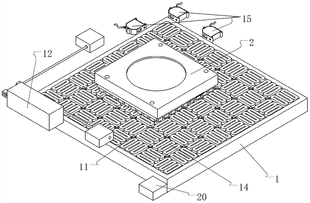
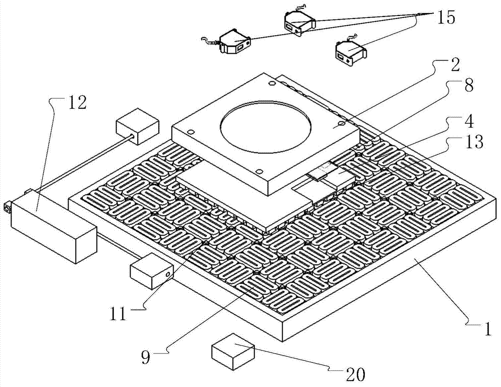
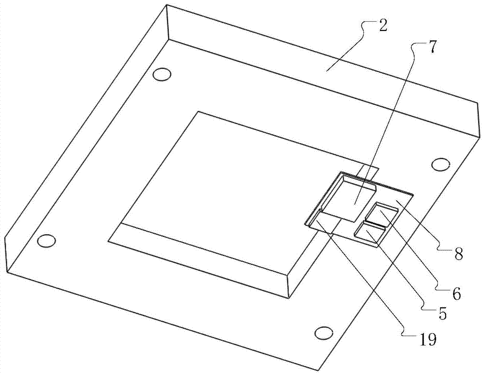
[0022] figure 1 , figure 2 A three-dimensional structure diagram of a moving iron-type cable-free six-degree-of-freedom maglev motion platform provided for the invention. The moving iron-type cable-free six-degree-of-freedom maglev motion platform includes a base 1, a stator, a mover, and a carrier. Table 2 and a measuring system, the mover is composed of a halbach permanent magnet array 13 and a magnetic steel back plate 4; the stator is a coil array 14 formed by multiple sets of coil units 9; the measuring system It includes a laser interferometer measurement system 12, an eddy current sensor 11 and a laser triangle sensor 15. A three-axis gyroscope 5 and a three-axis accelerometer are also provided in the groove between the mover and the stage 2 6. A power supply module 7 and a wireless signal output module 19; a wireless signal receiving module 20 is provided on the stator, the three-axis gyroscope 5, the three-axis accelerometer 6 and the power supply module 7, and the wireless signal output module 19 Integrated on a circuit board 8, such as figure 2 with image 3 As shown; the three-axis gyroscope 5 can respectively measure the angle of the mover around the X-axis, Y-axis and Z-axis; the three-axis accelerometer 6 can respectively measure the mover along the X-axis, Y-axis and Z The linear acceleration of the axis; the measurement signals of the three-axis gyroscope 5 and the three-axis accelerometer 6 communicate wirelessly with the wireless signal receiving module 20 arranged on the stator through the wireless signal output module 19; The eddy current sensors 11 are arranged in an array in the gap between the coil units 9 of the stator, and the probe of the eddy current sensor 11 is placed vertically upward; three laser triangulation sensors 15 are provided at one corner of the stator, among which There are two laser triangle sensors 15 along the X direction, and one laser triangle sensor 15 along the Y direction. The three laser triangle sensors together with the eddy current sensor 11 are the three-axis gyroscope 5 and the three-axis acceleration Calculate 6 for calibration of six degrees of freedom.
[0023] The coil array 14 is formed by multiple groups of coil units 9 arranged along the X direction and the Y direction, each group of coil units includes at least 3 square coils, and two adjacent groups of coil units are arranged orthogonally.
[0024] Figure 5 shows several different structural forms adopted by the coil unit of the present invention, and a total of five are listed. The coil unit can adopt a stack of orthogonally wound coil groups (such as Figure 5a ), or use a single layer of rectangular coils arranged orthogonally from bottom to top to form a horizontal coil group (such as Figure 5b ), or a coil group with rectangular coils placed horizontally (such as Figure 5c ), or use rectangular coils to vertically place the coil group (such as Figure 5d ), or the use of laminated orthogonal printed PCB circuit coil groups (such as Figure 5e ); The number of each coil group is a multiple of three, and each coil is composed of an energized wire and a coil frame 10.
[0025] Figure 6 shows the structure of two permanent magnet arrays of the mover of the present invention. The permanent magnet array of the mover consists of a main permanent magnet and an attached permanent magnet 18. The main permanent magnet (the first main permanent magnet 16, the second main permanent magnet) The magnet 17) and the attached permanent magnet 18 are bonded and fixed on the surface of the magnetic steel back plate 4 in the form of a Halbach one-dimensional array or a two-dimensional planar array. The magnetic field directions of the adjacent main permanent magnet and the attached permanent magnet are perpendicular to each other. A closed magnetic circuit is formed between the permanent magnets.
[0026] The working process of the present invention is as follows:
[0027] The direction of the magnetic field generated by the permanent magnet array of the maglev platform, the direction of the current in the energized coil, and the direction of the Lorentz force generated are perpendicular to each other; each group of coil units can simultaneously be in two directions perpendicular to each other in the plane of the permanent magnet array, And provide thrust in the three degrees of freedom perpendicular to the plane direction of the permanent magnet array.
[0028] In this embodiment, as figure 1 As shown, first, the stator coil of the maglev motion platform is powered on. Since most of the sensors of the measurement system are incremental measurements, the sensor calibration is required at this time. The three laser triangulation sensors 15 arranged at one corner of the stator of the maglev platform and the eddy current sensor 11 on the coil array 14 are used to calibrate the zero position. There are two laser triangle sensors 15 along the X direction, which can measure the position of the mover of the maglev platform along the X direction and the inclination angle of rotation around the Z axis. A laser triangle sensor 15 is provided along the Y direction to measure the maglev movement. The position of the mover of the moving platform along the Y direction; the array of eddy current sensors 11 located on the coil array 14 can measure the position of the mover of the maglev moving platform along the Y direction, and the inclination angle of the mover around the X axis and the Y axis. After completing the above process, it can be determined that the maglev platform mover is located at the stator of the maglev platform. At the same time, the initial position of the three-axis gyroscope 5 and the three-axis accelerometer 6 installed on the maglev platform mover can be determined. Position, because the three-axis gyroscope 5 will drift after working for a period of time, so the above zero calibration process needs to be repeated continuously, such as Figure 4 Shown.
[0029] After the initial position calibration of the three-axis gyroscope 5 and the three-axis accelerometer 6 is completed, the laser interferometer measurement system 12 needs to be adjusted. First, the wireless signal output module 19 and the wireless signal receiving module 20 continuously notify the control system of the position signals of the three-axis gyroscope 5 and the three-axis accelerometer 6, and the measurement signal of the wireless signal transmission can be WIFI, Bluetooth or infrared. Through the control system, the position of the mover of the maglev platform in the magnetic field is continuously adjusted, and then the laser interferometer is adjusted to make it work normally within the allowable range. So far, the adjustment of the laser interferometer measurement system 12 is completed; in the maglev platform Under normal working conditions, the laser interferometer measuring system 12 is required for high-precision position measurement.
[0030] The power supply mode of the three-axis gyroscope 5 and the three-axis accelerometer 6 is to install a power module 7 on the circuit board 8. The power module 7 is a replaceable power module or a power module capable of wireless charging. When the maglev motion platform runs to the laser During the zero calibration process of the triangle sensor 15 and the eddy current sensor 11, a manipulator is used to replace the power module 7 or to wirelessly charge the power module 7. In summary, the maglev movement platform realizes a cable-free design.

PUM

no PUM

Description & Claims & Application Information

We can also present the details of the Description, Claims and Application information to help users get a comprehensive understanding of the technical details of the patent, such as background art, summary of invention, brief description of drawings, description of embodiments, and other original content. On the other hand, users can also determine the specific scope of protection of the technology through the list of claims; as well as understand the changes in the life cycle of the technology with the presentation of the patent timeline. Login to view more.

Similar technology patents

Multi-station three-dimensional laser scanning internal measurement device and method for volume of vertical tank with large length-diameter ratio

ActiveCN112378473Ahigh precision measurementPoint cloud data with the same accuracy
Owner:HARBIN INST OF TECH

Rapid centering optical element center thickness precision measuring instrument

PendingCN112985228ASimple structurehigh precision measurement
Owner:西安应用光学研究所

Sensing instrument

InactiveUS20100024532A1detect variation accuratelyhigh-precision measurement
Owner:NIHON DEMPA KOGYO CO LTD

Digital image measuring system

PendingCN111895906Ahigh precision measurementhigh resolution
Owner:ENDIAN SCI & TECH DEV OF YUNNAN

Classification and recommendation of technical efficacy words

  • high precision measurement
  • Improve anti-interference ability

High-accuracy remote absolute displacement measurement system based on optical fiber composite interference

InactiveCN102564317Ahigh precision measurement
Owner:BEIJING JIAOTONG UNIV

Calibrating device for large-range continuous optical path delay line

ActiveCN103743552AHigh measurement accuracyhigh precision measurement
Owner:HARBIN ENG UNIV

Ultraviolet temperature measuring method and apparatus for MOCVD epitaxial wafer surface temperature measurement

ActiveCN105136310Ahigh precision measurementSimple structure
Owner:UNIV OF ELECTRONIC SCI & TECH OF CHINA

Composite electromagnetic shielding paint based on nano carbon material

InactiveCN105331264AImprove anti-interference abilityGood protection against electromagnetic radiation
Owner:INST OF URBAN ENVIRONMENT CHINESE ACAD OF SCI
Why Eureka
Try Eureka