[0039] The content of the present invention will be further described below in conjunction with the drawings and embodiments.
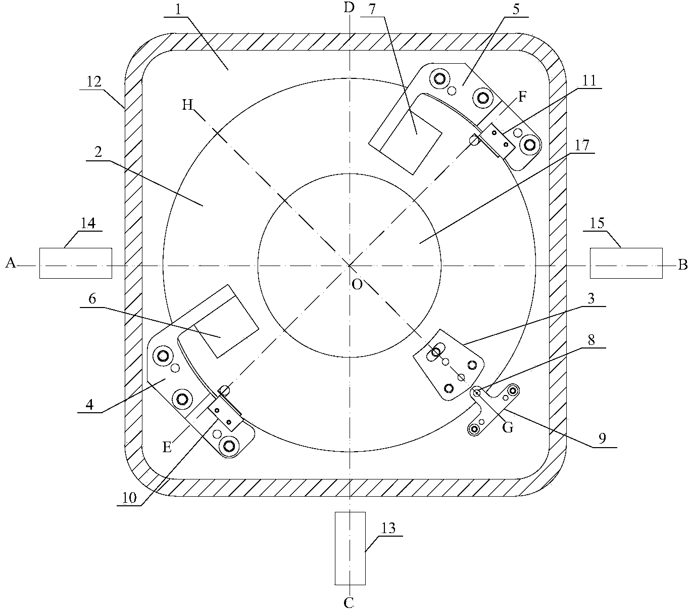
[0040] Such as figure 1 As shown, the three-channel switching device provided by this embodiment includes a stator 1, a rotor 2, a positioning block 3, a first positioning bracket 4, a second positioning bracket 5, a first electromagnet 6, a second electromagnet 7, and a photocell 8. , Photocell holder 9, first travel switch 10, second travel switch 11, photoelectric code disc (not shown in the figure), housing 12, controller 19 and driving device 20.
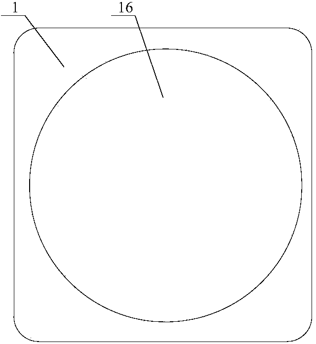
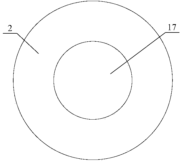
[0041] Such as figure 2 As shown, the stator 1 has a rectangular shape, and a circular through hole 16 is provided inside. Such as image 3 As shown, the rotor 2 has a cylindrical shape with a circular cavity 17 provided therein, for example. The rotor 2 is arranged in the through hole 16 of the stator 1, and the inner diameter of the through hole 16 matches the outer diameter of the rotor 2 so that the rotor 2 can rotate in the through hole 16 of the stator 1. The positioning block 3 is fixed on the upper end surface of the rotor 2 so that the rotor 2 can drive the positioning block 3 to rotate. The material of the positioning block 3 is iron, for example. In this embodiment, the positioning block 3 is fixed to the upper end surface of the rotor 2 by, for example, bolts.
[0042] The first positioning bracket 4 and the second positioning bracket 5 are both L-shaped. The long arms of the first positioning bracket 4 and the second positioning bracket 5 are fixed on the upper end surface of the stator 1 near the rotor 2. The first positioning bracket 4 and The short arms of the second positioning bracket 5 are all located above the upper end surface of the rotor 2, and the first positioning bracket 4 and the second positioning bracket 5 are located on the same straight line EF. In this embodiment, the long arms of the first positioning bracket 4 and the second positioning bracket 5 are fixed to the upper end surface of the stator 1 near the rotor 2 by, for example, bolts. The short arms of the first positioning bracket 4 and the second positioning bracket 5 are both close to the upper end surface of the rotor 2, and the short arms of the first positioning bracket 4 and the second positioning bracket 5 are not in contact with the upper end surface of the rotor 2.
[0043] The first electromagnet 6 is located above the upper end surface of the rotor 2, and the first electromagnet 6 is fixed on the short arm of the first positioning bracket 4. The second electromagnet 7 is located above the upper end surface of the rotor 2, and the second electromagnet 7 is fixed on the short arm of the second positioning bracket 5. Preferably, the first electromagnet 6, the second electromagnet 7, the short arm of the first positioning bracket 4 and the short arm of the second positioning bracket 5 are located on the same horizontal plane. Both the first electromagnet 6 and the second electromagnet 7 are used to attract the positioning block 3 so that the positioning block 3 is stationary. In this embodiment, the flatness of the suction surfaces of the first electromagnet 6 and the second electromagnet 7 reaches the micron level to ensure that the positioning block 3 can be accurately positioned at the position of the second channel 14 or the third channel 15.
[0044] The first travel switch 10 is fixed on the long arm of the first positioning bracket 4. In this embodiment, the first travel switch 10 is fixed to the long arm of the first positioning bracket 4 by, for example, bolts. The first travel switch 10 is used to send a first travel instruction signal to the controller 19 when the positioning block 3 rotates to the position where the first travel switch 10 is located. The second travel switch 11 is fixed on the long arm of the second positioning bracket 5. In this embodiment, the second travel switch 11 is fixed to the long arm of the second positioning bracket 5 by, for example, bolts. The second travel switch 11 is used to send a second travel instruction signal to the controller 19 when the positioning block 3 rotates to the position where the second travel switch 11 is located. The first limit switch 10 and the second limit switch 11 are located on the same straight line EF.
[0045] The photocell holder 9 is fixed on the upper end surface of the stator 1. The photocell 8 is fixed on the photocell holder 9, and the line GH between the photocell 8 and the center point O of the rotor 2 is perpendicular to the straight line EF, that is, the photocell 8 is 90 degrees to the first travel switch 10 and the second travel switch 11, respectively. Degree angle. The photoelectric encoder is arranged on the top of the outer circumferential surface of the rotor 2 (not shown in the figure). There is a uniform angle scale on the photoelectric code wheel. The photoelectric tube 8 is used to read the angle data of the photoelectric code disc and send the angle data to the controller 19 in real time.
[0046] Such as Figure 4 As shown, the controller 19 is electrically connected to the first electromagnet 6, the second electromagnet 7, the photocell 8, the first travel switch 10, the second travel switch 11, and the driving device 20, respectively. The driving device 20 is used to provide driving force to the rotor 2. The controller 19 is used to control the first electromagnet 6, the second electromagnet 7 and the driving device 20.
[0047] The casing 12 is wrapped around the outside of the stator 1 to protect the three-channel switching device. The first channel 13, the second channel 14 and the third channel 15 are arranged outside the three-channel switching device. The second channel 14 and the third channel 15 are located on the same straight line AB, that is, an angle of 180 degrees is formed between the second channel 14 and the third channel 15. The line CD between the first channel 13 and the center point O of the rotor 2 is perpendicular to the straight line AB, that is, the first channel 13 forms an angle of 90 degrees with the second channel 14 and the third channel 15 respectively.
[0048] Such as Figure 5 with Image 6 As shown, the rotor 2 is provided with a first light transmission hole 18. The stator 1 is provided with a second light-transmitting hole 21 in the direction facing the first channel 13, that is, the stator 1 is provided with a second light-transmitting hole 21 along the line OC. The housing 12 is provided with a third light-transmitting hole 22 in the direction facing the first channel 13, that is, the housing 12 is provided with a third light-transmitting hole 22 along the straight line OC direction. The stator 1 is provided with a fourth light transmission hole 23 in the direction facing the second channel 14, that is, the stator 1 is provided with a fourth light transmission hole 23 along the line OA direction. A fifth light transmission hole 24 is provided in the housing 12 in the direction toward the second channel 14, that is, a fifth light transmission hole 24 is provided in the housing 12 along the line OA direction. The stator 1 is provided with a sixth light transmission hole 25 in the direction facing the third channel 15, that is, the stator 1 is provided with a sixth light transmission hole 25 along the line OB. A seventh light transmission hole 26 is provided in the housing 12 in a direction toward the third channel 15, that is, a seventh light transmission hole 26 is provided in the housing 12 along the line OB. The first light transmission hole 18, the second light transmission hole 21, the third light transmission hole 22, the fourth light transmission hole 23, the fifth light transmission hole 24, the sixth light transmission hole 25, the seventh light transmission hole 26, the The first channel 13, the second channel 14 and the third channel 15 are all located in the same horizontal plane.
[0049] The three-channel switching method provided in this embodiment adopts the above-mentioned three-channel switching device, and the three-channel switching method includes the following steps:
[0050] S1: When starting to work, the positioning block 3 is located at the initial position, that is, at point G. At this time, the first light transmission hole 18 of the rotor 2 faces the first channel 13, that is, the first light transmission hole 18 of the rotor 2 is along the straight line OC ,Such as figure 1 with Figure 5 Shown; at this time, the optical signal from the first channel 13 can be sequentially transmitted to the cavity 17 of the rotor 2 through the third light-permeable hole 22, the second light-permeable hole 21 and the first light-permeable hole 18;
[0051] S2: After the controller 19 receives the first channel switching signal from the user, the controller 19 sends the first driving instruction signal to the driving device 20, and the driving device 20 drives the rotor after receiving the first driving instruction signal from the controller 19 2 drives the positioning block 3 to rotate in the direction of the second channel 14; when the rotor 2 starts to rotate, the photocell 8 starts to read the angle data of the photoelectric encoder and sends the angle data to the controller 19 in real time; when the positioning block 3 rotates to When the first travel switch 10 is at the position, that is, when the positioning block 3 rotates to the linear OE direction, the first travel switch 10 sends a first travel instruction signal to the controller 19; the controller 19 receives the first travel instruction signal from the first travel switch 10 After the first stroke instruction signal, the first stop instruction signal is sent to the drive device 20, and at the same time the controller 19 sends the first pull-in instruction signal to the first electromagnet 6; the drive device 20 receives the first stop instruction signal from the controller 19 After the command signal, it stops providing driving force to the rotor 2. The rotor 2 and the positioning block 3 continue to rotate in the direction of the second channel 14 by inertia; the first electromagnet 6 generates a magnetic effect after receiving the first pull-in command signal from the controller 19 The magnetic force can attract the positioning block 3 and fix the positioning block 3 to the second channel 14, that is, fix the positioning block 3 in the straight line OA direction. At this time, the first transparent hole 18 of the rotor 2 faces the second channel 14, such as Image 6 with Figure 7 As shown, the switching from the first channel 13 to the second channel 14 is completed so far; at this time, the optical signal from the second channel 14 can sequentially pass through the fifth light transmission hole 24, the fourth light transmission hole 23, and the first light transmission hole. The light hole 18 is transmitted into the cavity 17 of the rotor 2;
[0052] S3: After the controller 19 receives the second channel switching signal from the user, the controller 19 sends a separation command signal to the first electromagnet 6, and at the same time the controller 19 sends a second driving command signal to the driving device 20; After an electromagnet 6 receives the separation command signal from the controller 19, the magnetic force disappears, and the driving device 20 drives the rotor 2 to drive the positioning block 3 to rotate in the direction of the third channel 15 after receiving the second driving command signal from the controller 19 ; When the rotor 2 restarts to rotate, the photoelectric tube 8 starts to re-read the angle data of the photoelectric encoder and sends the angle data to the controller 19 in real time; when the positioning block 3 rotates to the position of the second travel switch 11, That is, when the positioning block 3 rotates to the straight line OB direction, the second travel switch 11 sends a second travel instruction signal to the controller 19; the controller 19 receives the second travel instruction signal from the second travel switch 11 and then drives the device 20 Send a second stop command signal, and at the same time, the controller 19 sends a second pull-in command signal to the second electromagnet 7; the driving device 20 stops providing driving force to the rotor 2 after receiving the second stop command signal from the controller 19 , The rotor 2 and the positioning block 3 continue to rotate in the direction of the third channel 15 by inertia; the second electromagnet 7 generates a magnetic force after receiving the second pull-in command signal from the controller 19, which can pull and position Block 3 and fix the positioning block 3 at the third channel 15, that is, fix the positioning block 3 in the direction of the straight line OB. At this time, the first light-transmitting hole 18 of the rotor 2 faces the third channel 15, such as Figure 8 As shown, the switching from the second channel 14 to the third channel 15 is completed so far; at this time, the optical signal from the third channel 15 can sequentially pass through the seventh light transmission hole 26, the sixth light transmission hole 25 and the first transmission The light hole 18 is transmitted into the cavity 17 of the rotor 2.
[0053] Repeating the above steps S2 and S3 can realize the repeated switching between the second channel 14 and the third channel 15.
[0054] The switch from the third channel 15 to the first channel 13 can be realized by adopting the switching device and the switching method of the prior art, which will not be repeated here.
[0055] Compared with the three-channel switching device in the prior art, the three-channel switching device of this embodiment brakes and positions the rotor in a manner that an electromagnet attracts the positioning block, avoiding the use of a motor to directly drive the rotor to brake and position the rotor. The collision deceleration process at the time, shortens the braking time of the rotor, and the electromagnet can lock the position of the rotor, which improves the positioning accuracy of the rotor, thereby improving the speed and accuracy of channel switching.
[0056] It should be understood that the above detailed description of the technical solutions of the present invention with the aid of preferred embodiments is illustrative and not restrictive. A person of ordinary skill in the art can modify the technical solutions described in each embodiment or make equivalent substitutions to some of the technical features on the basis of reading the specification of the present invention; these modifications or substitutions do not make the corresponding technical solutions The essence deviates from the spirit and scope of the technical solutions of the embodiments of the present invention.