Electric vehicle and method for controlling same
An electric vehicle, travel control technology, applied in electric vehicles, vehicle rescue, motor vehicles and other directions
- Summary
- Abstract
- Description
- Claims
- Application Information
AI Technical Summary
Problems solved by technology
Method used
Image

Examples
Embodiment approach 1
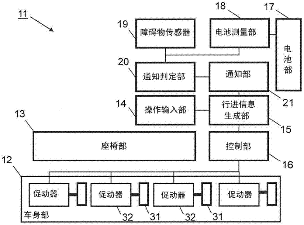
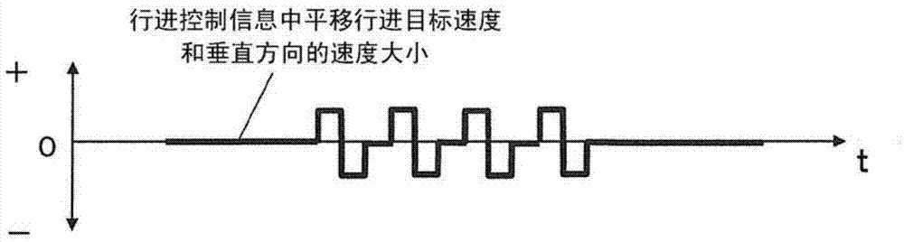
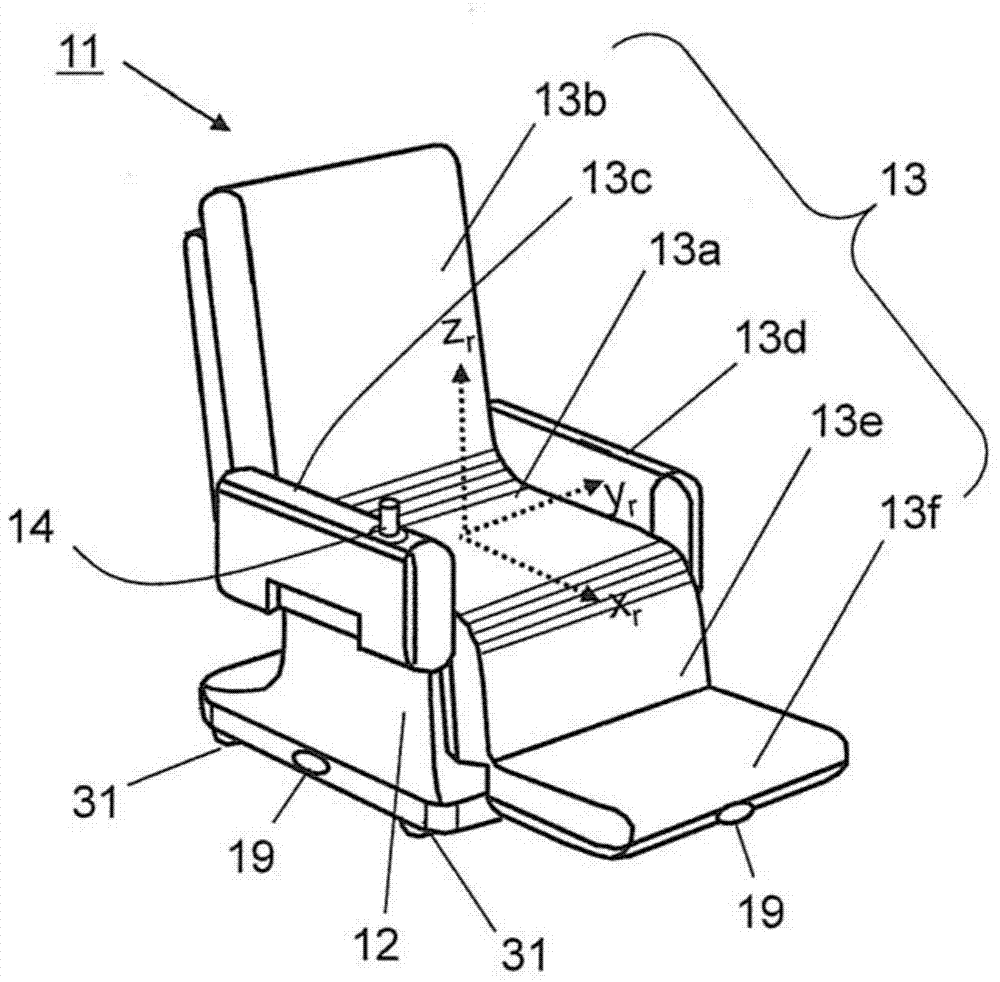
[0045] figure 1 , figure 2 , image 3 , Figure 4 It is a drawing for explaining the electric vehicle 11 according to Embodiment 1 of the present invention. figure 1 is a schematic configuration diagram of the electric vehicle 11, figure 2 It is a time chart of the traveling control information indicating the direction of the speed of the traveling target in translation and the magnitude of the speed in the vertical direction. image 3 is a perspective view of the electric vehicle 11 according to Embodiment 1, Figure 4 It is a plan view of the electric vehicle 11 according to the first embodiment.
[0046] Such as figure 1 , figure 2 , image 3 , Figure 4 As shown, the electric vehicle 11 according to Embodiment 1 is an electric wheelchair that moves by the operation of a driver seated on the seat portion 13 . Also, for ease of understanding, a vehicle coordinate system Σr (with three mutually orthogonal x r axis, y r axis, z r axis coordinate system). by...
Embodiment approach 2
[0103] Figure 17 , Figure 18 It is a drawing used for explaining the electric vehicle 51 which concerns on Embodiment 2 of this invention, Figure 17 is a perspective view of the electric vehicle 51, Figure 18 is a plan view of the electric vehicle 51 .
[0104] Next, regarding this second embodiment, while referring to the attached Figure 1 Differences from Embodiment 1 will be described. Such as Figure 17 , Figure 18 As shown, the electric vehicle 51 is an electric transport trolley that is pushed (or pulled) by a driver to move.
[0105] The electric vehicle 51 is equipped with: a body part 52; a handle part 53, which is an operation input part for detecting an input operation direction and an operation amount; Rotate travel target speed), generate travel control information according to the travel target speed; the control unit 16. In addition, the handle portion 53 is a driver contact portion provided on the vehicle body portion 52 .
[0106] The handle por...
Embodiment approach 3
[0110] Figure 19 , Figure 20 It is a drawing used for explaining the electric vehicle 61 which concerns on Embodiment 3 of this invention, Figure 19 is a perspective view of the electric vehicle 61, Figure 20 is a plan view of the electric vehicle 61 .
[0111] Next, regarding the present embodiment 3, while referring to the appended Figure 1 Differences from Embodiment 1 will be described. Such as Figure 19 , Figure 20 As shown, the electric vehicle 61 is an electric wheelchair that moves according to the operation of a driver seated on the seat portion 13 as a driver contact portion. Compared with the electric vehicle 11 of Embodiment 1 that includes four wheels 31 and four actuators 32, the electric vehicle 11 of Embodiment 3 is different in that it includes two wheels 65a, 65b, and two actuators. Devices 66a, 66b and auxiliary casters 68.
[0112] The electric vehicle 61 is equipped with: a body part 62; a seat part 13, which is a driver's contact part provi...
PUM
 Abstract
Description
Claims
Application Information
 - R&D
- Intellectual Property
- Life Sciences
- Materials
- Tech Scout
- Unparalleled Data Quality
- Higher Quality Content
- 60% Fewer Hallucinations
Browse by: Latest US Patents, China's latest patents, Technical Efficacy Thesaurus, Application Domain, Technology Topic, Popular Technical Reports.
© 2025 PatSnap. All rights reserved.Legal|Privacy policy|Modern Slavery Act Transparency Statement|Sitemap|About US| Contact US: help@patsnap.com