Turbo charger control system and control method

A turbocharger and control system technology, applied in electrical control, engine control, machine/engine, etc., can solve the problems that exhaust gas cannot be restored and purified, exhaust flow heat loss, etc., to solve the problem of insufficient engine boost, effective Effects of using and preventing chaos

Active Publication Date: 2014-05-07
HITACHI ZOSEN CORP
View PDF7 Cites 7 Cited by
  • Summary
  • Abstract
  • Description
  • Claims
  • Application Information

AI Technical Summary

Problems solved by technology

[0028] The problem to be solved by the present invention is that in the existing turbocharger control system, when the denitrification reaction device is detoured,

Method used


Image

  • Turbo charger control system and control method
  • Turbo charger control system and control method
  • Turbo charger control system and control method

Examples


Example

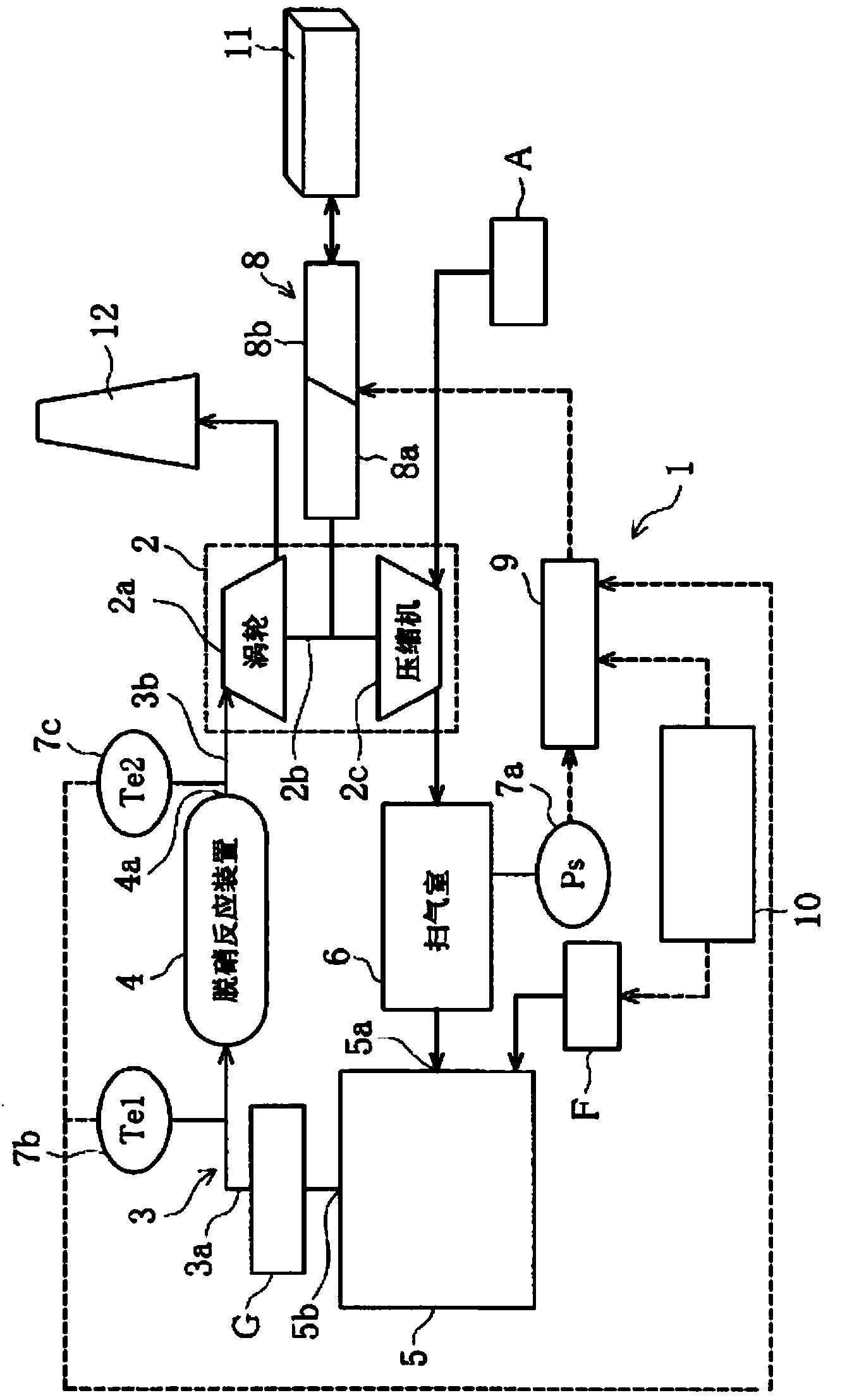
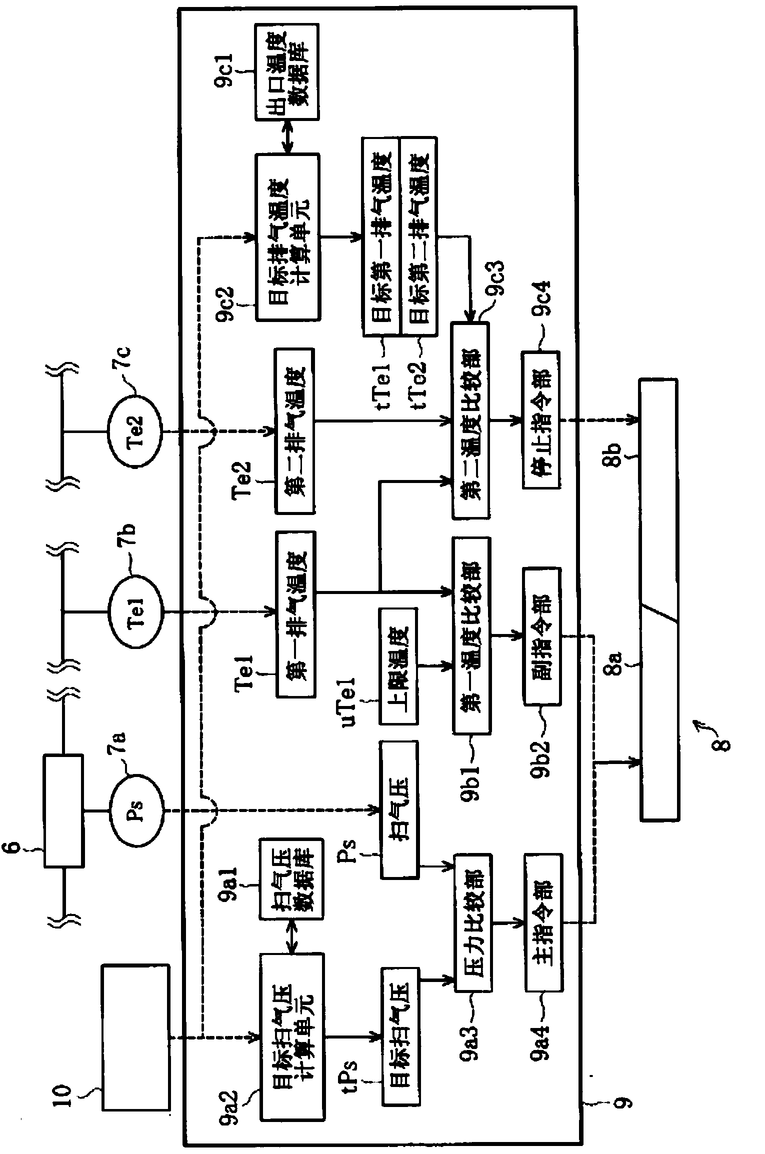
[0054] Such as figure 2 As shown, the control device 9 includes at least: a target sweep air pressure calculation unit 9a2, which accesses the sweep air pressure database 9a1, and obtains the target sweep air pressure tPs based on the engine revolution data acquired from the revolution control device 10; and a pressure comparison unit 9a3, Used to compare the sweep air pressure Ps of the scavenging chamber 6 detected by the pressure gauge 7a and the target sweep air pressure tPs obtained by the target sweep air pressure calculation unit 9a2; the main command unit 9a4, which controls the direction of the air based on the comparison result of the pressure comparison unit 9a3 The drive power supplied by the motor 8a simultaneously issues an instruction to the generator 8b to charge the power storage device 11 with the regenerative power of the motor 8a (first embodiment of the present invention).

[0055] The scavenging air pressure database 9a1 is a database in which the target sca...


PUM


Abstract

In an engine mechanism is provided with a de-nitrification reaction unit upstream of a turbine, to prevent hunting without providing a bypass path. The turbo charger control system is provided with: a pressure gauge (7a) to detect the air scavenging pressure (Ps) of the interior of an air scavenging chamber (6); a motor (8a) that can assist or dampen the operation of a turbocharger; a generator (8b) that can charge the regenerated power from the motor (8a) to an electricity storage device (11); and a control unit (9). The control unit (9) is provided with at least the following: an air scavenging pressure database (9a1); a target air scavenging pressure calculating means (9a2) that calculates the target air scavenging pressure (tPs); a pressure comparison unit (9a3) that compares the air scavenging pressure (Ps) and the target air scavenging pressure (tPs); and a main command unit (9a4) that controls the motor (8a) or the generator (8b) according to the results of the pressure comparison from the pressure comparison unit (9a3). All of the exhaust gas always undergoes purification treatment. The energy of the exhaust gas can be utilized effectively as electrical power for driving the motor without the loss of any energy.

Description

technical field [0001] The present invention relates to a turbocharger control system and its control method, which is applicable to the engine mechanism, wherein, the exhaust channel on the upstream side of the turbine of the turbocharger is provided with a device for reducing the nitrogen oxides (hereinafter referred to as "nitrogen oxides" in the exhaust gas) NO x ”) Reductive denitrification reaction device. Background technique [0002] Such as Figure 4 As shown in (a), generally, the turbocharger 101 includes a turbine 101b and a compressor 101c at both ends of a rotating shaft 101a, and utilizes the exhaust flow of high-temperature exhaust gas discharged from the exhaust port 103b of the engine 103 to the exhaust passage 104 to rotate the turbine 101b, and use this power to drive the compressor 101c. Then, the air compressed by the compressor 101c is supplied to the scavenging port 103a of the engine 103 through the scavenging chamber 102 . [0003] In this way, w...

Claims


Application Information

Patent Timeline
IPC IPC(8): F02B37/04F02B33/44
CPCF01N3/2066F01N5/04F01N11/002F01N2550/02F01N2560/06F01N2560/14F02B37/04F02B39/10F02D41/0007Y02T10/12Y02T10/40
Inventor 马场真二
Owner HITACHI ZOSEN CORP
Why Eureka
Try Eureka