Supercharge Your Innovation With Domain-Expert AI Agents!

Calibration method for delay asymmetry of high-precision optical fiber two-way time comparison equipment

A technology of two-way time comparison and calibration method, applied in the direction of transmission monitoring/testing/fault measurement system, etc., can solve the problem that the influence of optical fiber and cable cannot be deducted

Active Publication Date: 2017-01-04
SHANGHAI JIAOTONG UNIV
View PDF3 Cites 2 Cited by
  • Summary
  • Abstract
  • Description
  • Claims
  • Application Information

AI Technical Summary

Problems solved by technology

The German Federal Institute of Physics and Technology (Federal Institute of Physics and Technology) proposed a satellite-based optical fiber two-way time comparison method for equipment delay asymmetry (Rost, M., et al. "Time transfer through optical fibers over a distance of 73km with an uncertainty below 100ps."Metrologia49.6(2012):772.), but it cannot deduct the influence of optical fiber and cable on the accuracy of the equipment

Method used


Image

  • Calibration method for delay asymmetry of high-precision optical fiber two-way time comparison equipment
  • Calibration method for delay asymmetry of high-precision optical fiber two-way time comparison equipment
  • Calibration method for delay asymmetry of high-precision optical fiber two-way time comparison equipment

Examples


Embodiment Construction

[0038] A specific implementation example of the present invention is given below in conjunction with the accompanying drawings. This embodiment is carried out on the premise of the technical solution of the present invention, and a detailed implementation manner and a specific work flow are given, but the protection scope of the present invention is not limited to the following embodiments.

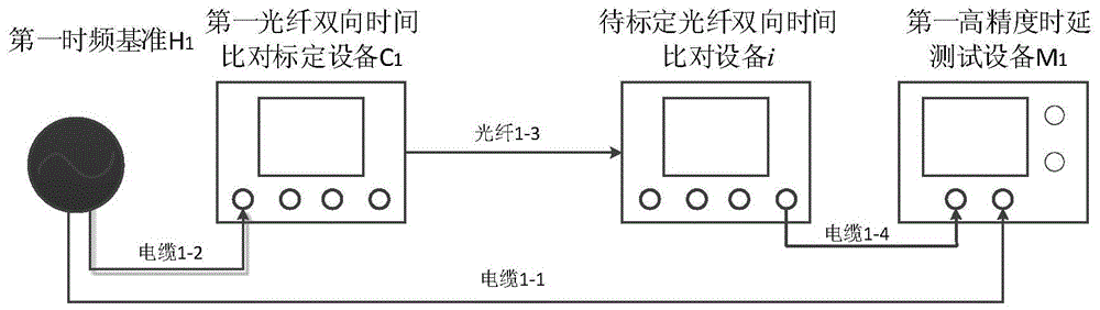
[0039]figure 1 It is a schematic diagram of the calibration of the delay difference of the receiving link, which is mainly composed of the first time-frequency reference H 1 , the first optical fiber two-way time comparison and calibration equipment C 1 , the optical fiber bidirectional time comparison device i (i=A, B) to be calibrated, the first high-precision time delay measurement device M 1 , cables and optical fibers. The first time-frequency reference H 1 (such as various atomic clocks) output timing information is divided into two ways. One channel of timing information is inp...


PUM


Abstract

The invention discloses a method for calibrating the time-delay asymmetry of high-accuracy optical fibre bidirectional time comparison devices. The method comprises the following steps: (1) establishing a time-delay calibration system for the optical fibre bidirectional time comparison devices; (2) calibrating a reception chain time-delay difference between the optical fibre bidirectional time comparison devices; (3) calibrating a reception chain time-delay difference between the optical fibre bidirectional time comparison devices; (4) calibrating time-delay asymmetry between the optical fibre bidirectional time comparison devices. The method disclosed by the invention is capable of simply and conveniently calibrating the asymmetry between the optical fibre bidirectional time comparison devices, and calibrating the time-delay asymmetry between random time-frequency devices, thus effectively overcoming the influence of the different time delays of optical fibres or cables on the time-delay accuracy.

Description

technical field [0001] The invention relates to a method for calibrating time delay of equipment in the field of optical fiber time synchronization, in particular to a method for calibrating asymmetry of time delay of high-precision optical fiber bidirectional time comparison equipment. Background technique [0002] Device delay refers to the additional delay generated when the signal passes through the device, which is an inherent characteristic of the device. High-precision optical fiber two-way time comparison sends and receives timing signals through optical fiber links for time synchronization. To obtain accurate time synchronization accuracy, it is necessary to deduct the delay asymmetry of the optical fiber time comparison equipment to obtain accurate clock difference. Therefore, the calibration accuracy of the time delay asymmetry of the optical fiber time synchronization equipment itself will directly affect the accuracy of the optical fiber time synchronization sys...

Claims


Application Information

Patent Timeline
Patent Type & Authority Patents(China)
IPC IPC(8): H04B10/07
Inventor 吴龟灵胡亮黄璜江少平陈建平
Owner SHANGHAI JIAOTONG UNIV
Features
  • R&D
  • Intellectual Property
  • Life Sciences
  • Materials
  • Tech Scout
  • Unparalleled Data Quality
  • Higher Quality Content
  • 60% Fewer Hallucinations
Learn More