Check patentability & draft patents in minutes with Patsnap Eureka AI!

Outdoor unit of air conditioner

A technology for outdoor units and air conditioners, applied in the field of outdoor units, can solve problems such as obstacles to the rotation of the blower, pressure and freezing of the heat transfer tubes of the heat exchanger, and achieve the effect of preventing deformation and preventing the deformation of the heat exchanger.

Active Publication Date: 2017-03-01
MITSUBISHI ELECTRIC CORP
View PDF4 Cites 0 Cited by
  • Summary
  • Abstract
  • Description
  • Claims
  • Application Information

AI Technical Summary

Problems solved by technology

It also causes the problem that the large amount of water remains on the bottom plate of the outdoor unit and freezes without being discharged outside the outdoor unit.
If the ice formed as described above gradually grows around the heat exchanger or the blower, it will hinder the rotation of the blower, or the heat transfer tube of the heat exchanger will be deformed due to pressure from the surroundings due to the ice.

Method used


Image

  • Outdoor unit of air conditioner
  • Outdoor unit of air conditioner
  • Outdoor unit of air conditioner

Examples


Embodiment approach 1

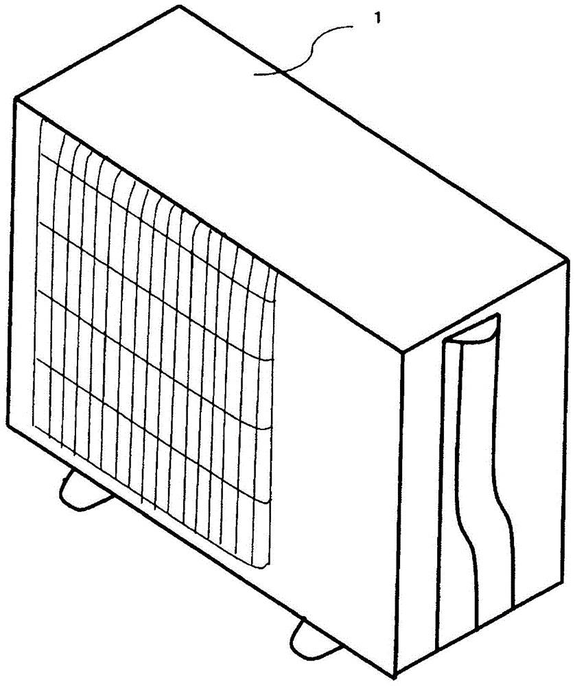
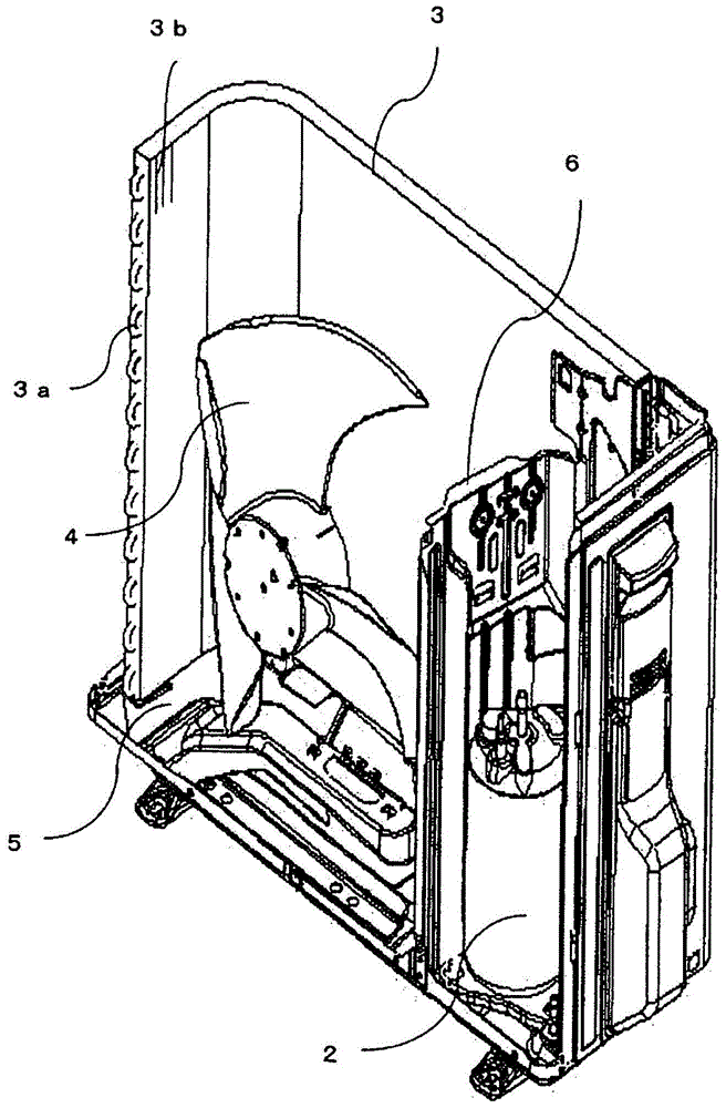
[0034] The outdoor unit of the air conditioner according to Embodiment 1 of the present invention will be described. figure 1 It is a perspective view showing the casing 1 of the outdoor unit of the air conditioner, which is made of a metal plate and formed into a substantially rectangular parallelepiped shape. in addition, figure 2 It is a perspective view showing the inside of the housing 1 with a part of the housing 1 removed. Such as figure 2 As shown, a compressor 2 for compressing refrigerant, an outdoor heat exchanger 3, a blower 4, and the like are accommodated inside the frame body 1 . The bottom plate 5 constituting the bottom of the frame body 1 is formed with mounting portions for various devices by, for example, press working, and the devices are mounted at various locations. Moreover, the partition wall 6 is formed between the part which accommodates the compressor 2, and the part which accommodates the heat exchanger 3 and the blower 4. As shown in FIG. Th...

Embodiment approach 2

[0066] Hereinafter, the outdoor unit of the air conditioner according to Embodiment 2 of the present invention will be described. In Embodiment 2, the structure in which the positioning wall for the heat exchanger 3 is provided in the flange 10 is demonstrated. In the drawings, the same reference numerals as those in Embodiment 1 denote the same or corresponding parts.

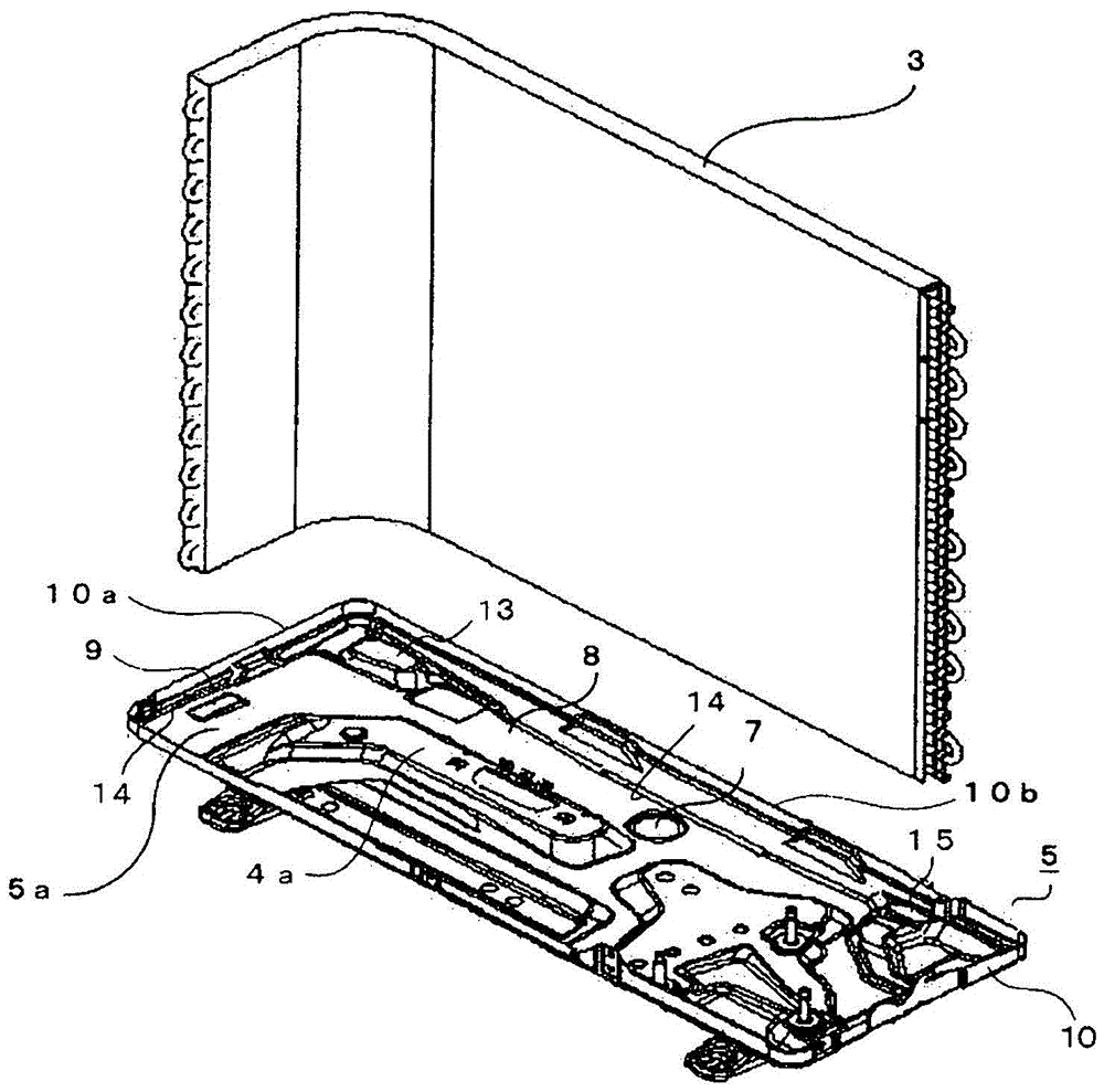
[0067] Figure 13 It is a top view showing the bottom plate 5 where the heat exchanger 3 and the blower 4 are accommodated. The positioning wall 12 is used to determine the installation position of the side surface of the heat exchanger 3 in the manufacturing process, and when the heat exchanger 3 is L-shaped, at least one positioning wall 12 is provided on each flange 10a, 10b. In this embodiment, there is one positioning wall 12 on the flange 10a and two positioning walls 12 on the flange 10b. in addition, Figure 14 yes Figure 13 The D-D line cross-sectional view also shows the heat exchanger 3 provid...


PUM


Abstract

The invention provides an outdoor unit of an air conditioner with high reliability, which can quickly discharge the drained water outside the outdoor unit without accumulating around the heat exchanger, and can prevent the drained water from freezing and causing the heat exchanger to deform. The bottom plate (5) constituting the bottom of the frame body (1) has: a bottom plate portion (5a); a flange (10) formed by turning upwards from the periphery of the bottom plate portion; a drainage hole (7) formed through the bottom plate portion, The drainage hole drains the water in the frame to the outside of the frame; the multiple mounting platforms (9, 13, 15) provided on the bottom plate protrude toward the inside of the frame at a predetermined distance from the flange, The lower end of the heat exchanger (3) is supported by its top surface (9a, 13a, 15a); and the drain groove (8) is connected to the mounting table and formed by a downward slope toward the drain hole. The bottom plate portion between the mounting table and the flange is composed of an inclined portion (11) inclined in the longitudinal direction of the flange and facing the drainage groove.

Description

technical field [0001] The present invention relates to an outdoor unit of an air conditioner, and more particularly to a drainage structure for discharging water. Background technique [0002] The outdoor unit of the air conditioner is formed of a substantially rectangular parallelepiped housing, and a compressor, an outdoor heat exchanger (hereinafter referred to as a heat exchanger), a blower, and the like are provided inside the housing. A partition wall is formed between the portion where the compressor is installed and the portion where the heat exchanger and the blower are installed. The heat exchanger is arranged in a substantially L-shape along the side surfaces of the housing. In addition, a drain hole penetrating through the base plate is formed on the base plate constituting the bottom of the housing, and water accumulated inside the housing is discharged to the outside through the drain hole. Therefore, the drainage hole is arranged at the lowest position of t...

Claims


Application Information

Patent Timeline
Patent Type & Authority Patents(China)
IPC IPC(8): F24F1/06F24F13/22
CPCF24F13/222F24F1/06F24F1/36F24F3/06
Inventor 岩崎弘久保野俊行大石一广山内秀高梁濑智也伊藤和穗
Owner MITSUBISHI ELECTRIC CORP
Features
  • R&D
  • Intellectual Property
  • Life Sciences
  • Materials
  • Tech Scout
  • Unparalleled Data Quality
  • Higher Quality Content
  • 60% Fewer Hallucinations
Learn More