Check patentability & draft patents in minutes with Patsnap Eureka AI!

Electromagnetic contactor

A technology of electromagnetic contactor and conductive plate, applied in electromagnetic relays, relays, detailed information of electromagnetic relays, etc., can solve problems such as weakening, and achieve the effect of increasing magnetic flux density

Active Publication Date: 2014-06-04
FUJI ELECTRIC FA COMPONENTS & SYST CO LTD
View PDF5 Cites 12 Cited by
  • Summary
  • Abstract
  • Description
  • Claims
  • Application Information

AI Technical Summary

Problems solved by technology

[0010] In the case of increasing the contact pressure by the contact spring in this way, there is an unsolved problem that the thrust force by the electromagnet driving the movable contact needs to be increased, resulting in an increase in the size of the overall configuration
However, there is an unsolved problem that, depending on the shape of the external connection conductor connected to the external connection terminal of the fixed contact of the electromagnetic contactor, the Lorentz force that suppresses the electromagnetic repulsion force in the separation direction is affected by the force flowing through the external connection conductor. The current is weakened by the influence of the magnetic field generated around the external connecting conductor

Method used


Image

  • Electromagnetic contactor
  • Electromagnetic contactor
  • Electromagnetic contactor

Examples


Embodiment Construction

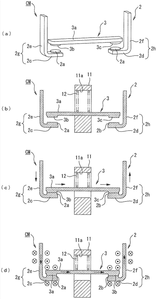
[0039] Hereinafter, embodiments of the present invention will be described with reference to the drawings. figure 1 It is a cross-sectional view showing an electromagnetic contactor to which the contact mechanism of the present invention is applied.

[0040] exist figure 1 Here, 1 is, for example, a main body case made of synthetic resin. The main body case 1 has a two-stage segmented structure of an upper case 1a and a lower case 1b. The contact mechanism CM is built in the upper case 1a. The contact mechanism CM includes a pair of fixed contacts 2 fixedly arranged on the upper case 1 a and a movable contact 3 arranged so as to be in contact with and detachable from the fixed contacts 2 .

[0041] Moreover, the operation electromagnet 4 which drives the movable contactor 3 is arrange|positioned in the lower case 1b. The operation electromagnet 4 is disposed so that a fixed core 5 formed of an E-shaped laminated steel plate faces a movable core 6 similarly formed of an E-s...


PUM


Abstract

Provided is an electromagnetic contactor that can suppress electromagnetic repulsion that causes a movable contactor to open during conduction, and to do so without enlarging the entire configuration or being impacted by the magnetic field of an external connection conductor. The present invention is provided with a contact mechanism (CM) comprising a fixed contactor (2) having a pair of fixed contact parts (2a, 2b) inserted in an electrical circuit, and a movable contactor (3) having a pair of moveable contact parts (3b, 3c) that can come in contact with or be separated from the pair of fixed connection parts. The shape of at least one of the pair of fixed contactor and the movable contactor is configured so as to be a shape that forms an electrical field that generates Lorentz force for opposing opening-direction electromagnetic repulsion generated between the fixed contactor and the movable contactor during conduction. Also, the present invention has external connection conductors (20, 21) that connect to external connection terminals (2i, 2j) of the fixed contactor (2), and the attachment direction of fixed parts (22, 23) attached to the external connection terminals of the external connection conductors is set to be a direction that intersects the direction of current flowing in the movable contactor.

Description

technical field [0001] The present invention relates to an electromagnetic contactor provided with a fixed contact and a movable contact inserted in a current path. The electromagnetic contactor generates a Lorentz force, and the Lorentz force resists and causes the movable contact to move from the fixed contact to the fixed contact when energized. The electromagnetic repulsion force of the contacts away. Background technique [0002] As an intermittent electromagnetic contactor for conducting a current path, conventionally, for example, an interrupter having a structure in which a fixed contact is bent so as to have a U-shape when viewed from the side, and a fixed contact is formed at a folded portion, The movable contact of the movable contact is provided on the fixed contact so as to be contactable and separable. In this interrupter, when breaking a large current, the electromagnetic repulsion force acting on the movable contact is increased to increase the breaking spee...

Claims


Application Information

Patent Timeline
IPC IPC(8): H01H50/54H01H50/14
CPCH01H50/14H01H1/54H01H50/546H01H50/10H01H1/58
Inventor 鹿志村修矶崎优立川裕之高谷幸悦中康弘柴雄二
Owner FUJI ELECTRIC FA COMPONENTS & SYST CO LTD
Features
  • R&D
  • Intellectual Property
  • Life Sciences
  • Materials
  • Tech Scout
  • Unparalleled Data Quality
  • Higher Quality Content
  • 60% Fewer Hallucinations
Learn More