Cleaning apparatus

A cleaning device and cleaning surface technology, which is applied in the direction of electrical components, semiconductor/solid-state device manufacturing, circuits, etc., can solve the problems of unremovable pollutants, unremovable pollutants, and adverse effects on wafer quality, so as to suppress adverse effects and reduce Effect of Backside Contamination

Inactive Publication Date: 2014-06-11
DISCO CORP
View PDF7 Cites 4 Cited by
  • Summary
  • Abstract
  • Description
  • Claims
  • Application Information

AI Technical Summary

Problems solved by technology

[0009] However, in the cleaning device configured to support the outer peripheral portion of the wafer with brushes, the contaminants present on the front side of the wafer may go around to the back side of the wafer, and the force of the brush contacting the back side may cause the contaminants to adhere to the wafer. The dorsal periphery cannot be removed
Therefore, there is a problem that if the wafer processing is continued without removing the contaminants, the contaminants adhering to the outer periphery of the back surface of the wafer cannot be removed even in other cleaning steps, thus adversely affecting the quality of the wafer.

Method used


Image

  • Cleaning apparatus
  • Cleaning apparatus
  • Cleaning apparatus

Examples


Embodiment Construction

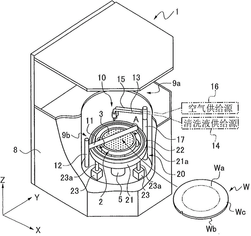
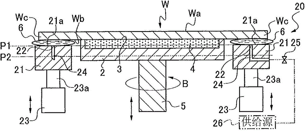
[0037] while referring to figure 1 as well as figure 2 The structure of the cleaning apparatus 1 for cleaning the wafer W which is the workpiece will be described. The cleaning device 1 has: a rotary table 2 for holding a workpiece and capable of high-speed rotation; a cleaning member 10 for cleaning the workpiece; and a peripheral holding member 20 formed to surround the rotary table 2 and support The outer peripheral portion of the workpiece, and the cleaning device 1 is configured to be accommodated in a space formed in the central portion of the container 8 .

[0038] Such as figure 1 as well as figure 2 As shown, the rotary table 2 is formed to have a diameter smaller than the outer diameter of the workpiece. The rotary table 2 has a porous member 4, and the surface side of the rotary table 2 is an upper surface 3 for suction holding a workpiece. The lower end of the rotary table 2 is connected to a rotary shaft 5 that rotates the rotary table 2 at high speed. In ...


PUM


Abstract

The invention provides a cleaning apparatus. In a rotary table, the cleaning apparatus can brush and clean a face to be cleaned of a wafer, and the back pollution caused by that pollutants go to the back of the wafer is prevented. A periphery holding member is provided with a liquid storing part; a liquid feeding opening; and an elevating part. Liquid is stored on upper surface (21a) of the liquid storing part to form a liquid layer; the liquid feeding opening supplies liquid to the upper surface of the liquid storing part; and the elevating part selectively positions the liquid storing part to an acting position and a non-acting position. Thus, when the wafer (W) is cleaned, the liquid storing part is positioned to the acting position, the upper surface (7) of the liquid layer formed on the liquid storing part and the upper surface (3) of the rotary table are at the same height, the liquid layer holds the periphery (Wc) of the wafer, and the front side (Wa) of the wafer is cleaned through a cleaning member. In addition, due to the fact that the back (Wb) of the wafer is sealed by the liquid layer, the pollutants are prevented from going to the back of the wafer, and the back pollution can be reduced.

Description

technical field [0001] The present invention relates to a cleaning device for cleaning the surface of a wafer. Background technique [0002] When a grinding device is used to grind both sides of a wafer cut out from an ingot and having undulations on both sides, or the back surface of a wafer having a plurality of devices formed on the surface divided by a spacer, since the wafer is attached to the swarf (contamination), so the wafer needs to be cleaned after grinding. In addition, after grinding the back surface of the wafer on which the devices are formed, when the wafer is divided into individual devices by separating the streets with a laser processing device or a dicing device, since cutting chips (contaminants) etc. are attached to the wafer, Therefore, it is also necessary to clean the wafer after separation. [0003] A general grinding device or cutting device has at least: a processing member, which is used to grind or cut a wafer held on a chuck table; a rotary c...

Claims


Application Information

Patent Timeline
Patent Type & Authority Applications(China)
IPC IPC(8): H01L21/67H01L21/683
CPCH01L21/67023H01L21/68735H01L21/68764H01L21/67034H01L21/67046
Inventor 沟本康隆
Owner DISCO CORP
Why Eureka
Try Eureka