Supercharge Your Innovation With Domain-Expert AI Agents!

Receiver/surge tank evacuation in vapor compression cooling systems with pumped refrigerant economizers

一种冷却系统、制冷剂的技术,应用在冷却系统领域,能够解决消耗掉等问题

Active Publication Date: 2018-11-02
VERTIV CORP
View PDF8 Cites 0 Cited by
  • Summary
  • Abstract
  • Description
  • Claims
  • Application Information

AI Technical Summary

Problems solved by technology

In other words, less than half of the power is consumed by the servers in the data center

Method used


Image

  • Receiver/surge tank evacuation in vapor compression cooling systems with pumped refrigerant economizers
  • Receiver/surge tank evacuation in vapor compression cooling systems with pumped refrigerant economizers
  • Receiver/surge tank evacuation in vapor compression cooling systems with pumped refrigerant economizers

Examples


Embodiment Construction

[0025] Example embodiments will now be described more fully with reference to the accompanying drawings.

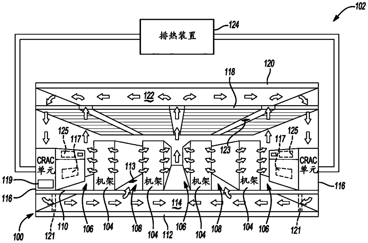
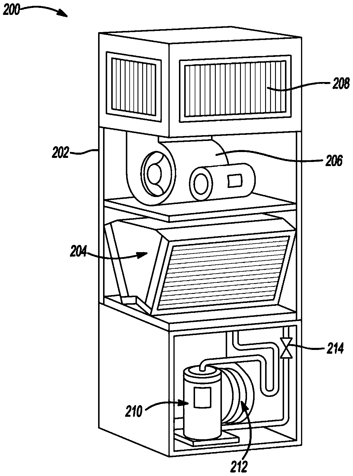
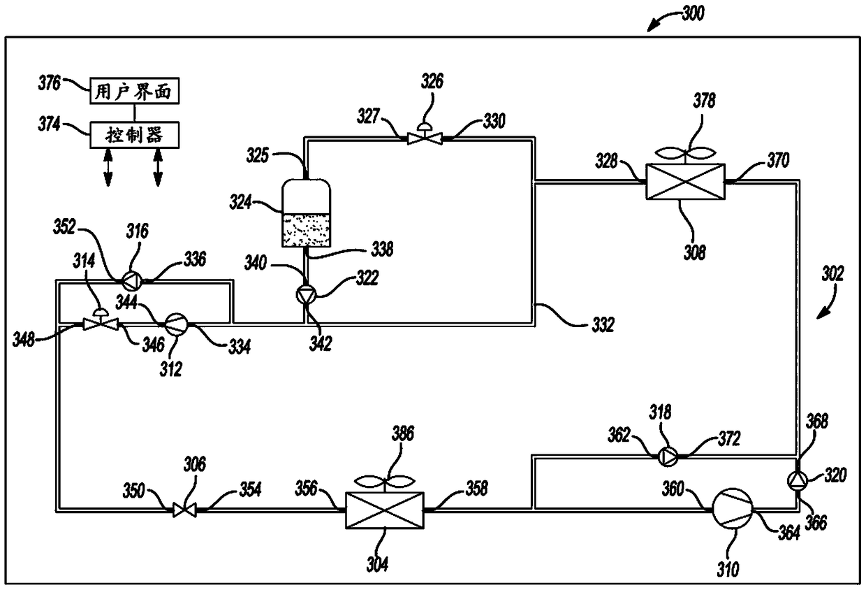
[0026] According to aspects of the present disclosure, a cooling system that may include a CRAC includes a DX cooling circuit with a pumped refrigerant economizer and a receiver / surge tank at an outside temperature sufficiently cool Cooling the cooling fluid circulating in the cooling circuit and bypassing the compressor enables the system to operate in pumped refrigerant economizer mode. The cooling fluid may illustratively be a phase change refrigerant having a vapor phase and a liquid phase. A pumped refrigerant economizer may illustratively include a pump that circulates a cooling fluid, illustratively refrigerant in its liquid phase, bypassing a compressor. This cooling system then uses a pump instead of a compressor to pump the refrigerant in its liquid phase when the outside air temperature is low enough to provide heat exchange without compressing the refrigerant...


PUM


Abstract

A cooling system includes a cooling circuit having an evaporator, a condenser, a compressor, an expansion device, a liquid pump, and a receiver / surge tank connected between the condenser and the liquid pump. This cooling system has a direct expansion mode and a pumped refrigerant economizer mode. When the cooling system switches from direct expansion mode to pumped refrigerant economizer mode, refrigerant is drained from the refrigerant / surge tank, allowing the cooling circuit to overfill when the cooling system begins operating in pumped refrigerant economizer mode.

Description

[0001] Cross References to Related Applications [0002] This application claims the benefit of US Provisional Application No. 61 / 734,416, filed December 7, 2012. The entire disclosure of the above application is incorporated herein by reference. technical field [0003] The present disclosure relates to cooling systems, and more particularly to high efficiency cooling systems. Background technique [0004] This section provides background information related to the present disclosure which is not necessarily prior art. [0005] Cooling systems can be used in many different applications where a fluid is to be cooled. Cooling systems are used to cool gases such as air and liquids such as water. Two common examples are heating, ventilation, air conditioning (HVAC) systems built for "comfort cooling", ie cooling spaces where people live, such as offices, and data center climate control systems. [0006] A data center is a room that includes a collection of electronic equipm...

Claims


Application Information

Patent Timeline
Patent Type & Authority Patents(China)
IPC IPC(8): F25B1/00F25B41/04F25B49/02H05K7/20F25B41/20
CPCF25B23/00F25B45/00F25B2400/0401F25B2400/0415F25B2400/16F25B2400/19F25B2600/13F25B49/02Y02B30/70
Inventor 蒂莫西·J·施拉德尔格雷格·哈吉斯蒂芬·西拉托
Owner VERTIV CORP
Features
  • R&D
  • Intellectual Property
  • Life Sciences
  • Materials
  • Tech Scout
  • Unparalleled Data Quality
  • Higher Quality Content
  • 60% Fewer Hallucinations
Learn More