Mold system provided with air-assisted forming mechanism

An air-assisted molding and mold technology, applied in the field of injection molds, can solve problems such as

Active Publication Date: 2014-07-23
浙江普耐姆塑业股份有限公司
4 Cites 2 Cited by

AI-Extracted Technical Summary

Problems solved by technology

Many plastic products have edges with large cross-sections. If they are formed into a hollow structur...

Method used

[0028] In order to stabilize the air injection block 6 and to facilitate demoulding after the injection molding of the plastic part 9, the present embodiment also includes a pressing block 7, a slider 8 and an inclined guide post 81. Wherein, two pressing blocks 7 are elongated, embedded in the groove 10, and pressed on both sides of the upper surface of the air injection block 6 respectively. Simultaneously, the two side walls inside the groove 10 are stepped, the air injection block 6 is located at the bottom, a part of the briquetting block 7 is pressed on the air injection block 6, and the other part is pressed on the upper step of the side wall of the groove 10 . The slider 8 is fixed on the cavity, and its upper surface is provided with two screw holes 800, through which it can be fixed to the side edge of the lower surface of the cavity. In the groove 10 , the slider 8 is located in the middle of the two pressing blocks ...

Abstract

The invention provides a mold system provided with an air-assisted forming mechanism. The mold system comprises a mold core, a mold cavity, a thimble, a thimble plate, a thimble fixing plate, mold legs, a fixed core plate and an air injection block, wherein the mold core is positioned below the mold cavity; the thimble is fixed on the thimble fixing plate; the thimble plate and the thimble fixing plate are overlapped into a whole; the mold legs are connected between the mold core and the fixed core plate; the thimble plate and the thimble fixing plate are arranged between the mold core and the fixed core plate in a way of moving upwards and downwards; the air injection block is cylindrical; an air channel is formed inside the air injection block along the length direction; an air inlet communicated with the air channel is formed in the outer end face of the air injection block; a projecting air nozzle for jetting high-pressure air into the mold cavity is arranged on the inner end face of the air injection block; a groove is formed in the side face of the mold core; the air injection block is embedded into the groove; the air nozzle extends into the mold cavity. By adopting the mold system, high-pressure air can be blown into the mold cavity during injection molding by using the air injection block, so that a cavity is formed in a plastic product.

Technology Topic

Injection airHigh pressure +2

Image

  • Mold system provided with air-assisted forming mechanism
  • Mold system provided with air-assisted forming mechanism
  • Mold system provided with air-assisted forming mechanism

Examples

  • Experimental program(1)

Example Embodiment

[0024] The present invention will be further described in detail below with reference to the drawings and specific embodiments.
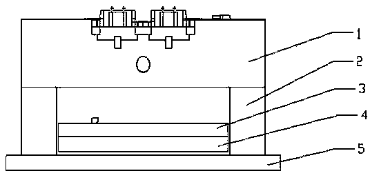
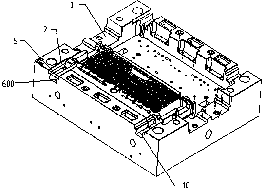
[0025] Such as figure 1 , figure 2 As shown, the embodiment of the present invention mainly includes a core 1, a cavity (not shown), a thimble (not shown), a thimble plate 3, a thimble fixing plate 4, a mold foot 2, a lower composite plate 5, and an air injection block 6. .
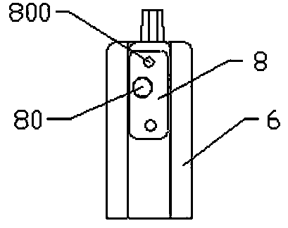
[0026] Specifically, the core 1 is located under the cavity, the thimble is fixed on the thimble fixing plate 4, the thimble plate 3 and the thimble fixing plate 4 are superimposed into one body, and the mold foot 2 is connected between the core 1 and the lower composite plate 5. The thimble plate 3 and the thimble fixing plate 4 are arranged between the core 1 and the lower composite plate 5 to be movable up and down. Another example 3- Figure 7 As shown, the air injection block 6 is cylindrical, with an air passage 60 along the length of the inside, an air inlet 600 communicating with the air passage 60 is provided on the outer end surface, and a protruding air nozzle 63 is provided on the inner end surface for the cavity Inject high-pressure air. The side of the core 1 is provided with a groove 10, the air injection block 6 is embedded in the groove 10, and the air nozzle 63 extends into the cavity.
[0027] Such as figure 2 , This embodiment is used for production Figure 8 , Picture 9 The plastic part 9 is shown, and two parts can be produced at the same time. Each product corresponds to two air injection blocks 6, and the air nozzles 63 of each two air injection blocks 6 correspond to the two ends of the edge of the plastic part 9, making the edges of the plastic part 9 hollow. Therefore, there are a total of four around the core 1. A groove 10.
[0028] In order to stabilize the air injection block 6 and facilitate demolding after the injection of the plastic part 9 is completed, this embodiment further includes a pressing block 7, a sliding block 8 and an inclined guide post 81. Among them, the pressing block 7 is a long strip, there are two, embedded in the groove 10, and pressed on both sides of the upper surface of the air injection block 6 respectively. At the same time, the two side walls inside the groove 10 are stepped, the air injection block 6 is located at the bottom, a part of the pressure block 7 is pressed on the air injection block 6 and the other part is pressed on the upper step of the side wall of the groove 10. The sliding block 8 is fixed on the cavity, and its upper surface is provided with two screw holes 800, and the screw holes 800 can be used to fix it on the side edge of the lower surface of the cavity. In the groove 10, the sliding block 8 is located in the middle of the two pressing blocks 7 and pressed on the upper surface of the air injection block 6. The air injection block 6 is provided with an outwardly inclined circular hole 610, and the slider 8 is provided with a defined hole 80 which is consistent with the inclination direction of the circular hole 610 and corresponds to each other. The upper end of the inclined guide post 81 is located in the defined hole 80, and the inclined guide The lower end of the column 81 is inserted into the circular hole 610. In addition, there is also a deep hole (not shown) corresponding to the circular hole 610 on the bottom surface of the groove 10 and in the same inclined direction to facilitate the insertion of the lower end of the inclined guide post 81.
[0029] More preferably, the upper surface of the inner end of the air injection block 6 is a boss 62 protruding upward, and the inner end of the pressing block 8 extends above the boss 62. The inclined guide post 81 is in the shape of a bolt, and the upper end of the limiting hole 80 is provided with a step, so that after the inclined guide post 81 is inserted, it will not fall down.
[0030] Such as Figure 8-9 As shown, the plastic part 9 has an edge 91 with a relatively large cross-section, which is a hollow structure with a through hole 910 inside. The through hole 910 cannot be formed by the prior art injection mold. When the plastic part 9 is produced in this embodiment, the air injection block 6, the pressing block 7, the sliding block 8, and the inclined guide post 81 are placed behind the groove 10, and the air nozzle 63 of the air injection block 6 extends into the cavity In, then close the mold. Then injection molding, while blowing high-pressure air through the air inlet 600. After the pressure is maintained, the mold is opened. At this time, the air nozzle 63 is located in the through hole 910, and the cavity is lifted upward, driving the sliding block 8 and the inclined guide post 81 to lift. The inclined guide post 81 is inclined, which will drive the air injection block 6 to slide outside the groove 10 At this time, the air nozzle 63 is separated from the through hole 910, so that the mold is opened smoothly.
[0031] In summary, the present invention can use the air assist mechanism to form a hollow structure in some of the plastic parts. Not only meets the strength requirements, but also saves materials.
[0032] It can be known from technical common sense that the present invention can be implemented by other embodiments that do not depart from its spirit or essential features. Therefore, the above-disclosed embodiments are only illustrative in all aspects, and not the only ones. All changes within the scope of the present invention or within the scope equivalent to the present invention are encompassed by the present invention.

PUM

no PUM

Description & Claims & Application Information

We can also present the details of the Description, Claims and Application information to help users get a comprehensive understanding of the technical details of the patent, such as background art, summary of invention, brief description of drawings, description of embodiments, and other original content. On the other hand, users can also determine the specific scope of protection of the technology through the list of claims; as well as understand the changes in the life cycle of the technology with the presentation of the patent timeline. Login to view more.
Why Eureka
Try Eureka