fuel supply device
A fuel supply device and fuel technology, applied in the direction of liquid fuel feeder, charging system, engine components, etc., can solve the problems of increased size of fuel supply device, difficulty in installing fuel tanks, etc.
- Summary
- Abstract
- Description
- Claims
- Application Information
AI Technical Summary
Problems solved by technology
Method used
Image


Examples
no. 1 approach )
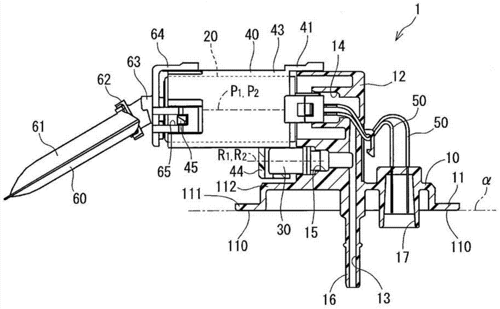
[0029] Figure 1~Figure 11C The fuel supply device of the first embodiment of the present invention is shown. The fuel supply device 1 of this embodiment is a turbo pump installed in a fuel tank of a motorcycle.
[0030] figure 2 as well as image 3 The fuel tank 2 of a motorcycle is shown. The fuel tank 2 is formed in a saddle shape, and the frame of the motorcycle passes through a recess 3 provided in the center of the fuel tank 2. The fuel supply device 1 is inserted into the fuel tank 2 from an opening 4 provided on the lower side of the tank in the direction of gravity. The fuel drawn up from the fuel tank 2 by the fuel supply device 1 is supplied to an internal combustion engine not shown.
[0031] Such as figure 1 as well as Figure 4 ~ Figure 6 As shown, the fuel supply device 1 includes a flange 10, a fuel pump 20, a regulator 30, a housing 40, and the like.
[0032] The flange 10 has a cover portion 11, a mounting portion 12, a discharge passage 13, and the like.
[003...
no. 1 approach
[0070] The first embodiment exerts the following effects.
[0071] (1) The fuel supply device includes a regulator 30 between the flange 10 and the fuel pump 20, and the rotation shaft P of the motor 24 of the fuel pump 20 1 And the moving direction R of the ball valve 32 of the regulator 30 1 It is parallel to the first imaginary plane α.
[0072] Thus, the fuel supply device 1 can reduce the size of the body of the flange 10 in the direction perpendicular to the first virtual plane α. Therefore, the fuel supply device 1 can be installed in a fuel tank 2 having a low height.
[0073] (2) The space S is provided on the opposite side of the regulator 30 from the discharge passage and on the flange side of the fuel pump 20.
[0074] With this space S, the fuel supply device 1 can be rotated inside the fuel tank 2, so the fuel supply device 1 can be easily assembled to the fuel tank 2.
[0075] Furthermore, by providing the regulator 30 in a region on the discharge passage side of the spa...
no. 2 approach )
[0099] Picture 12 A schematic diagram showing the fuel supply device of the second embodiment. In the second embodiment, the fuel pump 20 is arranged on the flange 10 and the regulator 30 is arranged on the fuel pump 20.
[0100] Also in the second embodiment, it is possible to exhibit substantially the same functions and effects as the above-mentioned first embodiment.
PUM
 Abstract
Description
Claims
Application Information
 - R&D
- Intellectual Property
- Life Sciences
- Materials
- Tech Scout
- Unparalleled Data Quality
- Higher Quality Content
- 60% Fewer Hallucinations
Browse by: Latest US Patents, China's latest patents, Technical Efficacy Thesaurus, Application Domain, Technology Topic, Popular Technical Reports.
© 2025 PatSnap. All rights reserved.Legal|Privacy policy|Modern Slavery Act Transparency Statement|Sitemap|About US| Contact US: help@patsnap.com