Check patentability & draft patents in minutes with Patsnap Eureka AI!

Measuring method and wireless measuring device for three-axis coordinates of base point in rock mass drilling

A three-dimensional coordinate, wireless measurement technology, applied in the field of rock mass mechanical parameter measurement, can solve the problems of easy bending and relaxation of steel wire, difficulty in installation, inconvenience in reading or collecting data, etc.

Active Publication Date: 2016-09-07
SICHUAN UNIV
View PDF5 Cites 0 Cited by
  • Summary
  • Abstract
  • Description
  • Claims
  • Application Information

AI Technical Summary

Problems solved by technology

However, the above two measurement methods have the following problems: (1) Since the base points have their own steel wires, each base point is successively pushed to different target points in the borehole, which is difficult to install, and the steel wires are easy to confuse and entangled, which will cause serious problems. Affect the acquisition of monitoring data in the later stage; (2) The premise of obtaining accurate displacement change value is to tighten the steel wire, but the steel wire is easy to bend and relax during on-site operation, which seriously affects the accuracy of monitoring data; (3) The above-mentioned drilling holes are many Both the point displacement meter and the roof abscission instrument need to be installed at the drilling hole on the roof of the rock roadway. Due to the complex mining conditions in the mine, it is very inconvenient to read or collect data. Simultaneous measurement has the disadvantage that the measurement efficiency is not high enough

Method used


Image

  • Measuring method and wireless measuring device for three-axis coordinates of base point in rock mass drilling
  • Measuring method and wireless measuring device for three-axis coordinates of base point in rock mass drilling
  • Measuring method and wireless measuring device for three-axis coordinates of base point in rock mass drilling

Examples


Embodiment Construction

[0041] The method for measuring the three-dimensional coordinates of the base point in the rock mass borehole and the wireless measuring device thereof according to the present invention will be further described below in conjunction with the accompanying drawings. It must be pointed out that the following examples are only used to further illustrate the present invention, and should not be interpreted as limiting the protection scope of the present invention. Those skilled in the art can make some non-essential improvements and adjustments to the present invention according to the above-mentioned content of the invention. The specific implementation still belongs to the protection scope of the present invention.

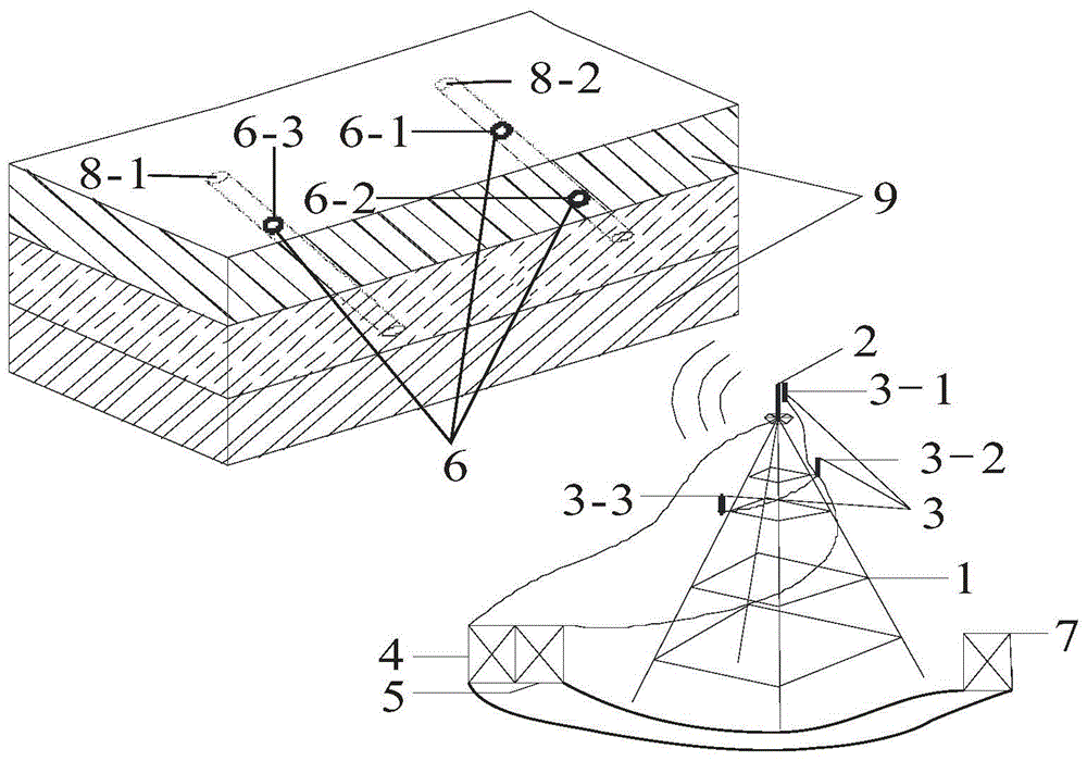
[0042] In this embodiment, the wireless signal reflector 6 is a hollow sphere made of copper, the outer diameter of the hollow sphere is 25mm, and the thickness of the shell is 5mm; the length of each transmitting antenna and receiving antenna is 20cm, and the chip i...


PUM


Abstract

The invention provides a method and wireless device for measuring three-dimensional coordinates of base points in rock mass drilling holes. The device comprises an installation tower, a transmitting antenna, a receiving antenna, a wireless signal projector, wireless signal receivers, wireless signal reflectors with chips, and a data processor. The transmitting antenna is installed on the installation tower and connected with the wireless signal projector, the wireless signal reflectors are installed at the various measured base points in the rock mass drilling holes, the receiving antenna is installed on the installation tower and is respectively connected with the wireless signal receivers, and the wireless signal receivers are connected with the data processor. The method comprises the steps that firstly, a three-dimensional coordinate system is established, the transmitting antenna, the receiving antenna and the measured base points in the rock mass drilling holes are located in the same three-dimensional coordinate system, and the three-dimensional coordinates of the top point of the receiving antenna bonded with the transmitting antenna serve as the origin of coordinates; secondly, the measuring device is started, the three-dimensional coordinates of the measured base points are calculated and stored.

Description

technical field [0001] The invention belongs to the field of rock mass mechanical parameter measurement, and relates to a method for measuring the three-axis coordinates of a base point in a rock mass borehole and a wireless measuring device thereof. Background technique [0002] In underground engineering, because the excavation operation destroys the original stress balance state of the rock mass, resulting in a certain degree of displacement, deformation and damage of the surrounding rock mass, and the stress of the surrounding rock mass is always in the process of dynamic changes, the displacement of the rock mass, Deformation and permeability characteristics also change accordingly. Rock mass displacement and deformation data are the basis of many parameters. Accurate acquisition of rock mass displacement and deformation data is an important guarantee for controlling the stability of rock mass and ensuring the smooth progress of the project. [0003] Especially in coal...

Claims


Application Information

Patent Timeline
Patent Type & Authority Patents(China)
IPC IPC(8): G01B15/06G01B15/00
Inventor 高明忠张茹谢晶徐晓炼谭强李圣伟
Owner SICHUAN UNIV
Features
  • R&D
  • Intellectual Property
  • Life Sciences
  • Materials
  • Tech Scout
  • Unparalleled Data Quality
  • Higher Quality Content
  • 60% Fewer Hallucinations
Learn More