Check patentability & draft patents in minutes with Patsnap Eureka AI!

Disengaging system

A separation system and clutch technology, applied in the field of separation systems, can solve problems such as line marks and sealing system failures

Active Publication Date: 2014-08-20
SCHAEFFLER TECH AG & CO KG
View PDF6 Cites 3 Cited by
  • Summary
  • Abstract
  • Description
  • Claims
  • Application Information

AI Technical Summary

Problems solved by technology

Furthermore, the known anti-rotation prevents rotation of the seal
The presence of tiny lines or foreign particles in the sealing surface can promote the formation of lines on the seal and premature failure of the sealing system

Method used


Image

  • Disengaging system
  • Disengaging system
  • Disengaging system

Examples


Embodiment Construction

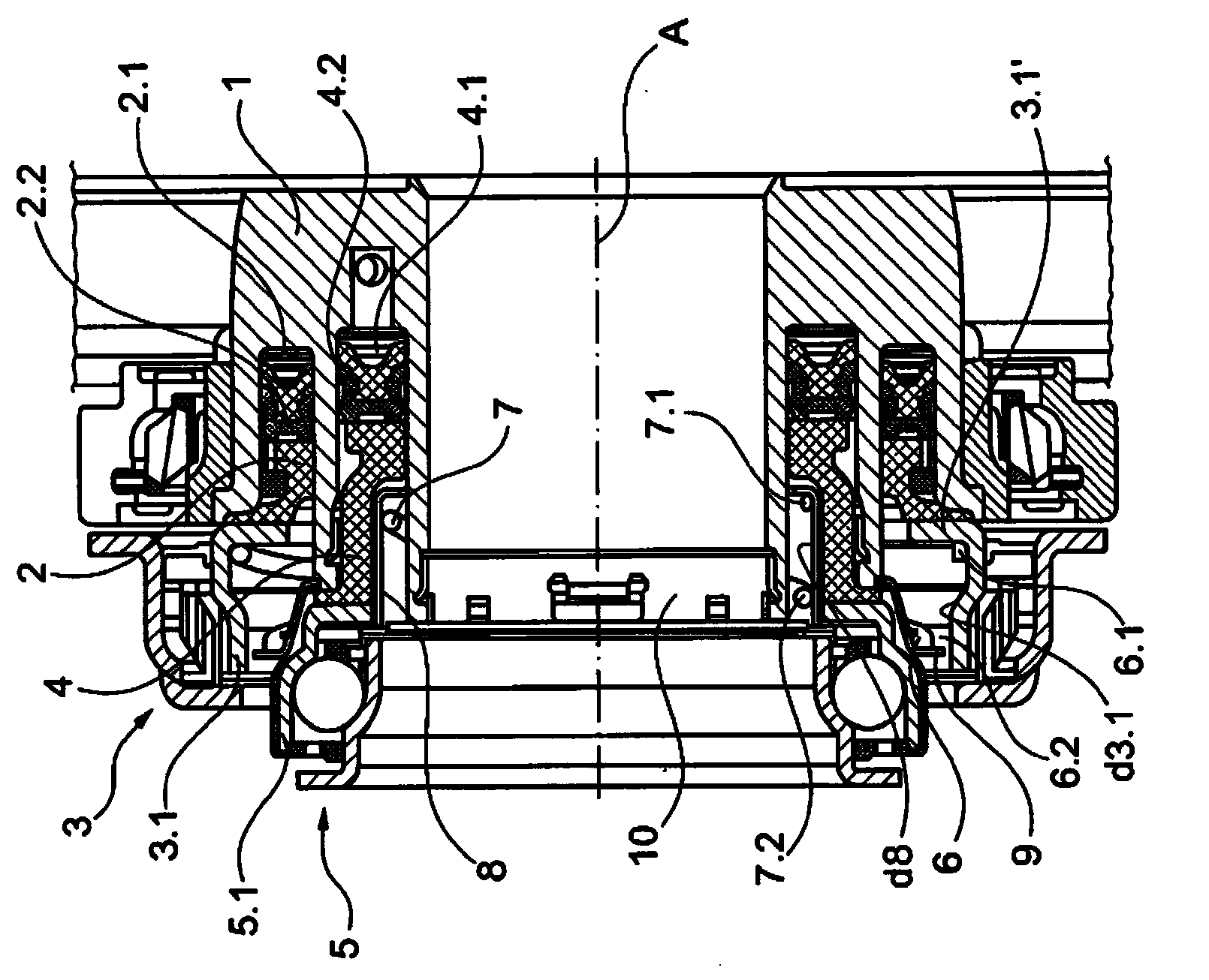
[0036] according to figure 1 , the slave cylinder is designed as a CSC centered slave cylinder and is used to actuate the dual clutch. The slave cylinder has a housing 1 in which a first piston 2 is arranged displaceably in the direction of a longitudinal axis A in a pressure chamber 2 . There is a first seal 2.2 on the first piston 2 in the direction of the first pressure chamber 2.1, and the first piston 2 acts at the end opposite to the first seal 2.2 against a radially outer first The radially inwardly facing region 3 . 1 ′ of the stationary / rotationally fixed first bearing ring 3 . 1 of the bearing 3 engages.

[0037] The second piston 4 is mounted axially displaceable concentrically within the first piston 2 in the second pressure chamber 4.1 and is sealed relative to the second pressure chamber 4.1 via a second seal 4.2. At the end opposite to the second seal 4.2, the second piston 4 acts on the radially inwardly facing region 5.1 of the stationary / rotationally fixed ...


PUM


Abstract

The invention relates to a disengaging system for operating a clutch, wherein the disengaging system is designed in particular in the manner of a CSC (concentric slave cylinder) and comprises at least one first piston displaceable along a longitudinal axis in a housing (1). The end of said piston facing towards a pressure chamber has a seal and at the region lying opposite the seal the piston acts on an engagement bearing (3, 5). According to the invention, in order to prevent rotation of a stationary bearing ring of the engagement bearing for supporting drag torques induced via the engagement bearing, at least one energy-storing element (6, 7) is integrated in the CSC and counteracts the drag torque with a tangential reaction torque (torsional moment).

Description

technical field [0001] The invention relates to a disengaging system for actuating a clutch according to the preamble of claim 1 , wherein the disengaging system is designed in particular in the form of a CSC (centered slave cylinder) and has a longitudinal At least one first piston which is displaced axially has a seal at its end facing the pressure chamber and which acts on an engagement bearing on a region opposite the seal. Background technique [0002] The clutch release system essentially consists of a housing in which a piston connected to a release bearing or a clutch bearing is guided axially. Since the release / engagement bearing is operatively connected to the loading device of the friction clutch, a drag torque is transmitted from the drive unit of the vehicle to the engagement bearing. The rotational bearing ring of the clutch bearing, which is fixed in the receptacle only via frictional contact, tends to rotate relative to the receptacle due to the drag torque,...

Claims


Application Information

Patent Timeline
IPC IPC(8): F16D25/08
CPCF16D25/083F16D2021/0669F16D23/14F16D2021/0661F16D25/10
Inventor 托马斯·拉姆霍费尔克里斯托弗·泽斯特吕本·克拉托夫马蒂厄·克劳斯
Owner SCHAEFFLER TECH AG & CO KG
Features
  • R&D
  • Intellectual Property
  • Life Sciences
  • Materials
  • Tech Scout
  • Unparalleled Data Quality
  • Higher Quality Content
  • 60% Fewer Hallucinations
Learn More