Check patentability & draft patents in minutes with Patsnap Eureka AI!

Machine tool parallel synchronous motion mechanism

A technology of synchronous motion and machine tools, which is applied in the direction of metal processing machinery parts, metal processing equipment, feeding devices, etc., can solve the problems of inconvenient operation of CNC machine tools, high production costs, etc., and achieve the effect of improving labor productivity and broad market prospects

Inactive Publication Date: 2016-03-16
重庆凤临智能机械装备制造有限公司
View PDF5 Cites 0 Cited by
  • Summary
  • Abstract
  • Description
  • Claims
  • Application Information

AI Technical Summary

Problems solved by technology

Not only does the production cost of the manufacturer remain high, but it also makes it inconvenient for the workers who operate the CNC machine tools

Method used


Image

  • Machine tool parallel synchronous motion mechanism

Examples


Embodiment Construction

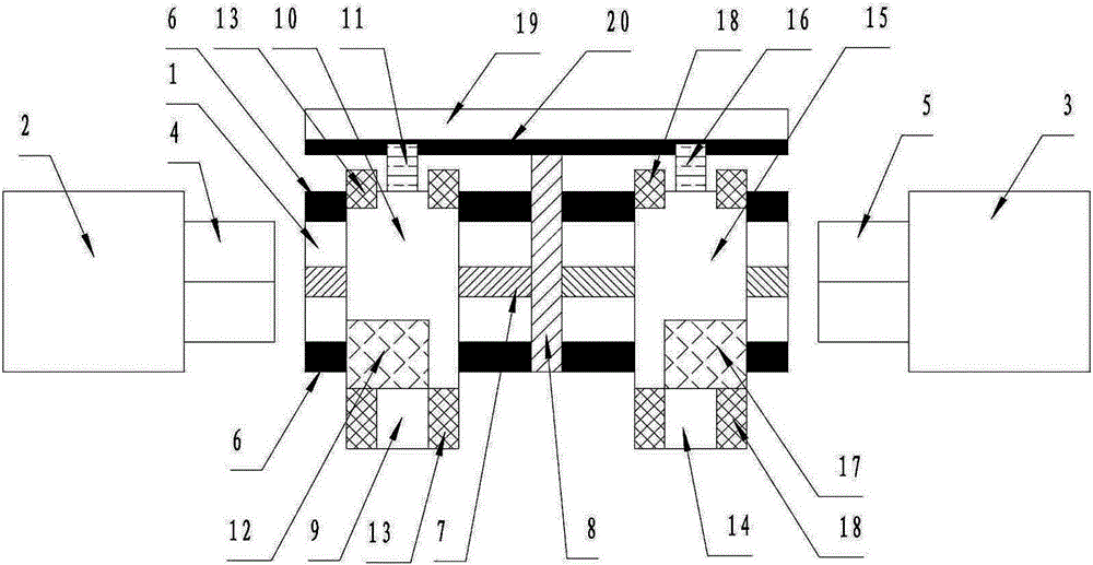
[0014] Such as figure 1 As shown, the parallel synchronous motion mechanism of the machine tool in this embodiment includes a machine bed 1, which is characterized in that one side of the machine bed 1 has a first headstock 2, and the other side of the machine bed 1 has a second Main shaft box 3, described first main shaft box 2 has first main shaft 4, and described second main shaft box 3 has second main shaft 5, and described first main shaft 4 is arranged opposite to second main shaft 5, and described first main shaft 4 There are longitudinal guide rails 6 on both sides of the machine bed 1 between the second main shaft 5, the longitudinal guide rails 6 are parallel to the first main shaft 4 and the second main shaft 5, and the middle part of the machine bed 1 has a longitudinal screw rod 7, so The machine tool bed 1 is provided with a transverse screw rod 8 arranged in a cross shape with the longitudinal screw rod 7, and there are respectively a first assembly and a second...


PUM


Abstract

The invention relates to a lathe parallel-connected synchronous motion mechanism comprising a lathe body. One side of the lathe body is provided with a first spindle box, the other side is provided with a second spindle box, the first spindle box is provided with a first spindle, and the second spindle box is provided with a second spindle; two sides of the lathe body are provided with longitudinal guide rails, a longitudinal screw is arranged in the middle of the lathe body, the lathe body is provided with a transverse screw, two sides of the transverse screw are provided with a first component and a second component, the first component comprises a first large carriage, a first medium carriage, a first linear guide rail block and a first cutter rest, two sides of the first component are provided with first component transverse guide rails, the second component comprises a second large carriage, a second medium carriage, a second linear guide rail block and a second cutter rest, and two sides of the second component are provided with second component transverse guide rails; one side of the transverse screw is connected to a parallel-connected synchronous frame through a screw nut, and the parallel-connected synchronous frame is provide with a linear guide rail. The mechanism is capable of actually playing the functions of numerical control systems, improving production efficiency and reducing cost.

Description

technical field [0001] The invention relates to a parallel synchronous motion mechanism of a machine tool. Background technique [0002] The existing numerical control technology is the development direction of the current equipment manufacturing industry. Generally speaking, in a numerical control equipment, the electrical part of numerical control accounts for about one-third of the cost of the machine tool. In order to maximize the functions of the numerical control system, improve production efficiency, and reduce costs, it is the goal pursued by those skilled in the art to be able to complete the processing of two or more products (parts) at one time. In order to achieve the goal, the existing machine tools are often designed in series. However, due to the limited installation space of the machine tool, the operation will be inconvenient after being connected in series. For example, in a CNC lathe, two spindles are installed on one side of the machine tool, and the ho...

Claims


Application Information

Patent Timeline
Patent Type & Authority Patents(China)
IPC IPC(8): B23Q5/40B23B19/02
CPCB23Q5/40
Inventor 邓立伟罗海峰彭小虎
Owner 重庆凤临智能机械装备制造有限公司
Features
  • R&D
  • Intellectual Property
  • Life Sciences
  • Materials
  • Tech Scout
  • Unparalleled Data Quality
  • Higher Quality Content
  • 60% Fewer Hallucinations
Learn More