
Backlight source simulation jig

A backlight and fixture technology, applied in optics, light guides, optical components, etc., can solve the problems of poor accuracy and long time (for example, it takes at least 12 hours to simulate under a server with 1 million light rays, and the results are biased, etc. Achieve the effect of saving development time, improving simulation accuracy and product simulation design efficiency

Inactive Publication Date: 2014-09-10
BOE TECH GRP CO LTD +1
View PDF4 Cites 7 Cited by
  • Summary
  • Abstract
  • Description
  • Claims
  • Application Information

AI Technical Summary

Problems solved by technology

Due to the limitations of the optical simulation software, the number of simulated rays is limited (such as tens of thousands, hundreds of thousands, etc.), and if the number of simulated rays is larger, the time taken for the simulation will be longer (such as 1 million It takes at least 12 hours to simulate under the optical server), so it can be seen that the results simulated by optical software have limitations, there will be deviations from the results in real samples, the accuracy is poor, and the simulation time is long

Method used


Image

  • Backlight source simulation jig
  • Backlight source simulation jig
  • Backlight source simulation jig

Examples


Embodiment Construction

[0049] The principles and features of the present invention are described below in conjunction with the accompanying drawings, and the examples given are only used to explain the present invention, and are not intended to limit the scope of the present invention.

[0050] In view of the prior art, before product development and design, the estimation and evaluation of the Hot Spot of the backlight is mainly realized through empirical summary and optical software simulation, which has the problems of poor accuracy and long time. The present invention provides a The backlight simulation fixture has a simple structure, which can improve simulation accuracy and product simulation design efficiency, and save development time.

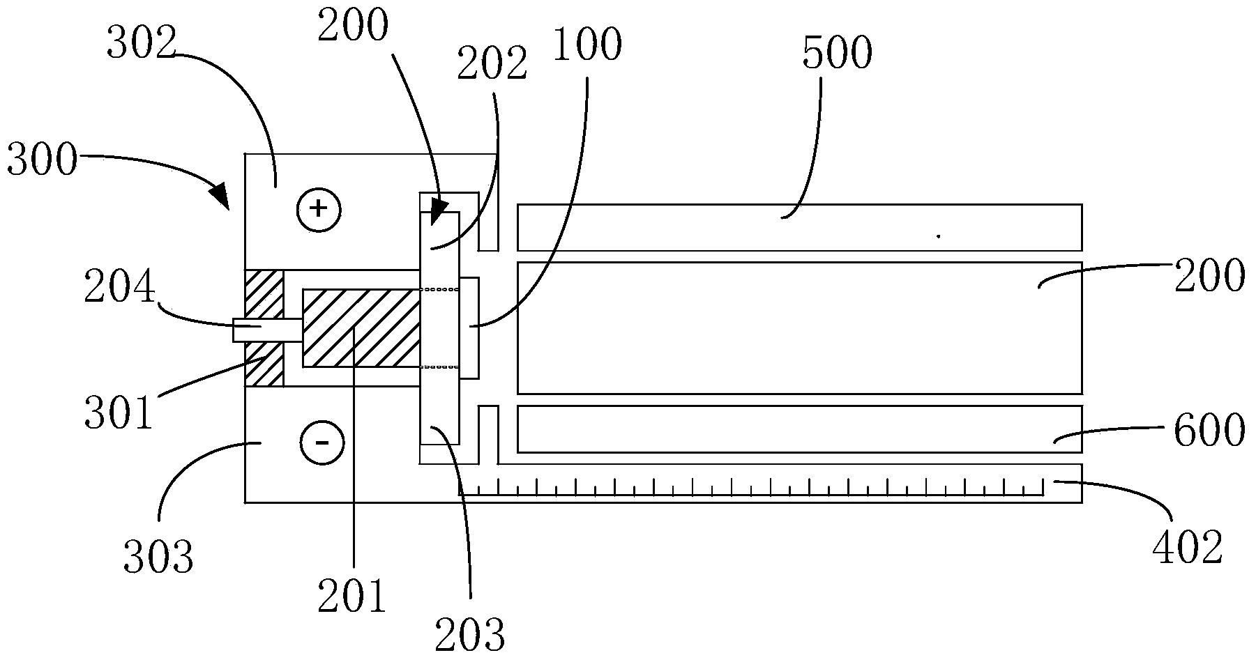
[0051] like image 3 and Figure 5 As shown, the backlight simulation fixture provided by the present invention includes:

[0052] A light source simulation part, the light source simulation part is provided with a plurality of movable light emitting compo...


PUM


Abstract

The invention provides a backlight source simulation jig which comprises a light source simulation part, an optical component simulation part, a first distance measurement unit and a second distance measurement unit, wherein a plurality of movable luminous parts are arranged on the light source simulation part; the optical component simulation part is arranged on one side of the luminous surfaces of the luminous parts, and comprises a light guide plate, and the relative positions of the luminous parts and the light guide plate can be changed; the first distance measurement unit is used for acquiring the distance between every two adjacent luminous parts; the second distance measurement unit is used for acquiring the distance between the luminous parts and the light guide plate. According to the backlight source simulation jig, main factors influencing the Hot Spot generation of a backlight source can be quantitatively controlled, optical effects of a backlight source product to be developed can be practically simulated, the generation conditions of Hot Spot can be accurately simulated, quantitative judgments about states in which a Hot Spot-free design is formed can be made by changing the abovementioned parameters, a foundation is laid for accurate design, the simulation accuracy and the product simulation design efficiency are improved, and the development time is saved.

Description

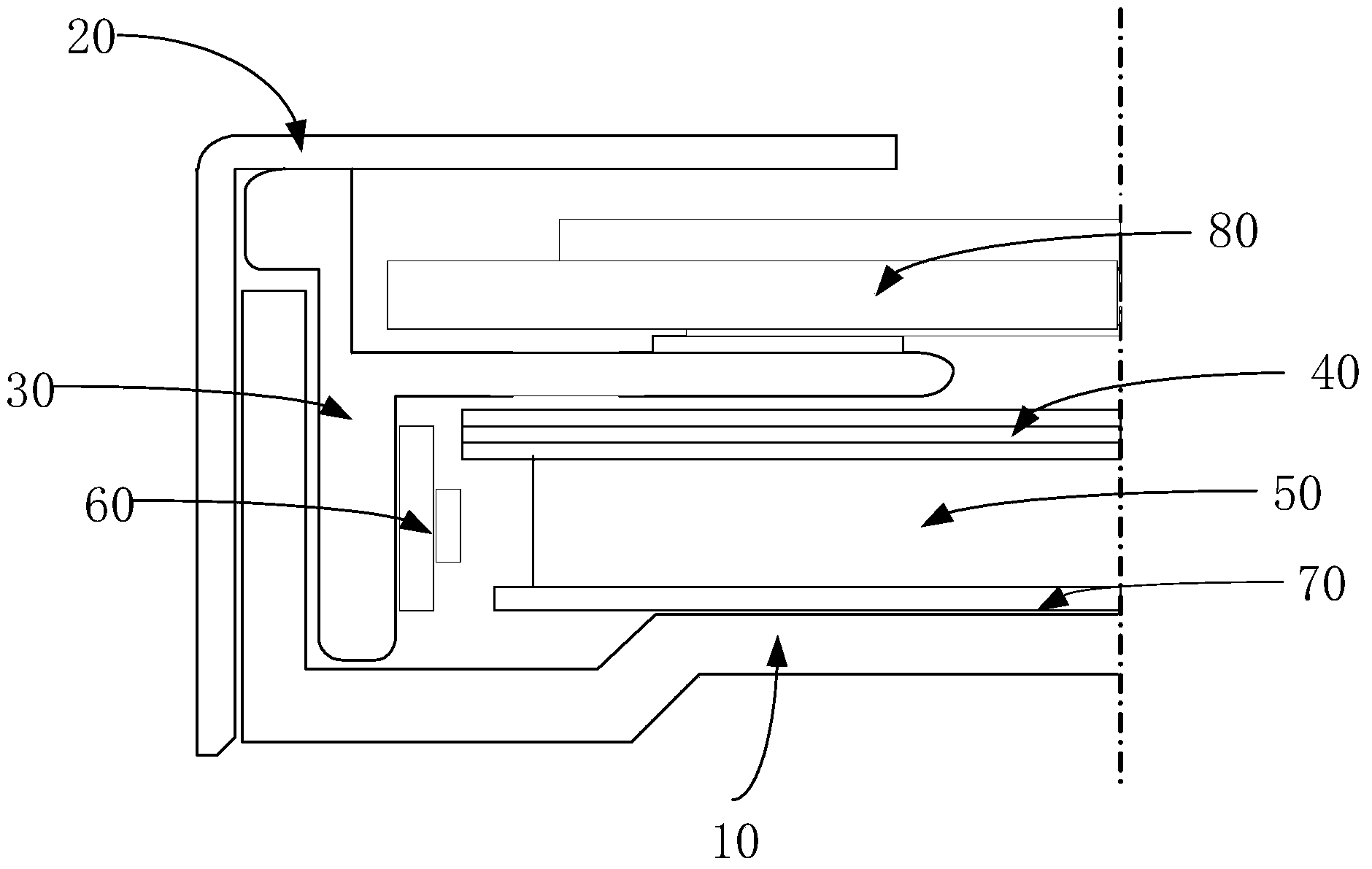
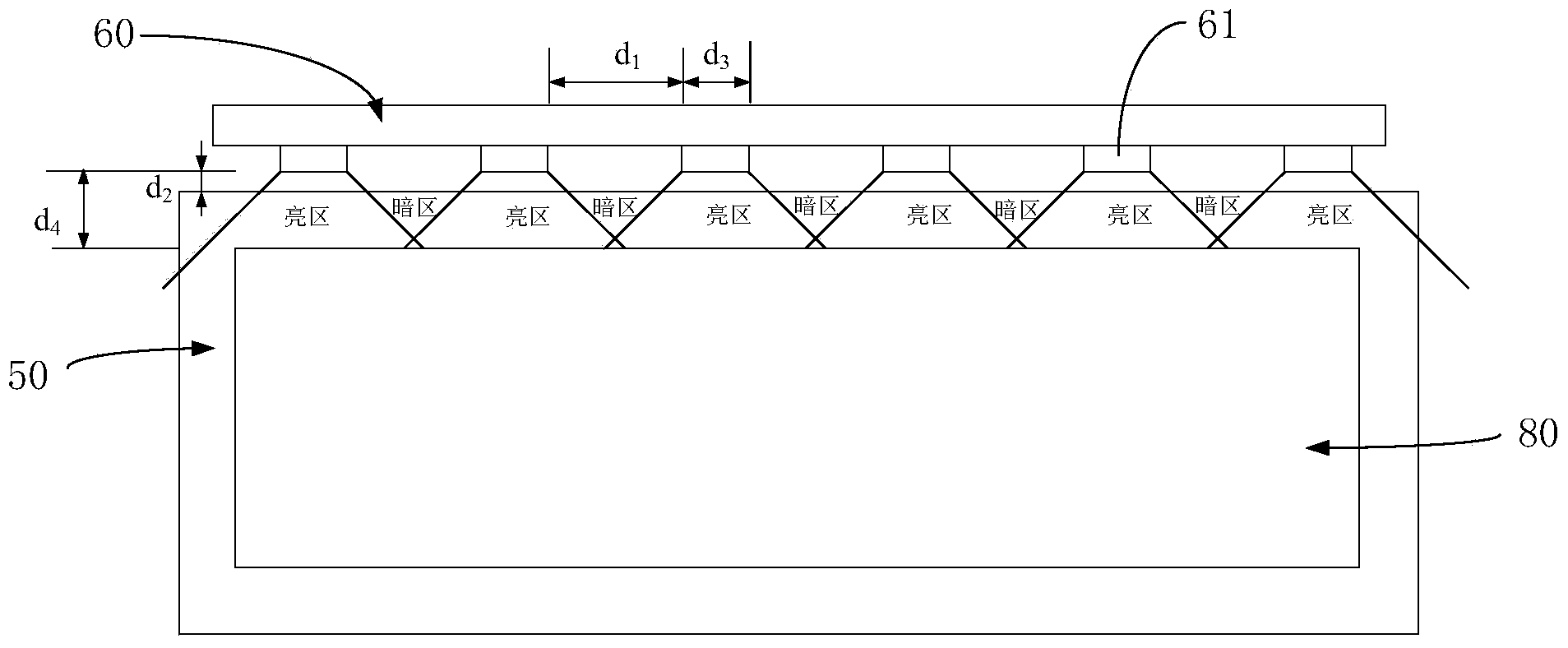
technical field [0001] The invention relates to the field of display technology, in particular to a backlight simulation fixture. Background technique [0002] Due to the advantages of low operating voltage, low power consumption, flexible display methods, and low radiation, Liquid Crystal Displays (LCDs) are widely used in various fields, such as computers, mobile phones, televisions, and measurement displays. The LCD includes a liquid crystal display panel and a backlight, and the backlight is used to provide a light source for the liquid crystal display panel so that the LCD can display images. like Figure 1 to Figure 3 As shown, the backlight usually includes a back cover (Back Cover) 10, a frame (Bezel) 20, a plastic frame (Mold Frame) 30, an optical film (Optical Sheet) 40, a light guide plate (LGP) 50 and an LED light bar 60, etc. , wherein the LED light bar 60 is arranged on one side of the light incident surface of the light guide plate 50, the light emitted by th...

Claims


Application Information

Patent Timeline
IPC IPC(8): G02F1/13
CPCG02B6/0013G02B6/009G02B6/0068G02B6/0031G02B6/005G02B6/0073G02B6/0088G02B6/0091
Inventor 颜凯柏玲鹿堃布占场
Owner BOE TECH GRP CO LTD
Learn More