Check patentability & draft patents in minutes with Patsnap Eureka AI!

Method To Make Curved Tubular Element And Curved Tubular Element Thus Obtained

A technology for bending pipes and bending parts, applied in the direction of pipe elements, pipes/pipe joints/fittings, elbows, etc., capable of solving complex and other problems

Inactive Publication Date: 2014-09-24
CIFA
View PDF3 Cites 21 Cited by
  • Summary
  • Abstract
  • Description
  • Claims
  • Application Information

AI Technical Summary

Problems solved by technology

However, this method is also complex and requires specialized equipment and long execution times

Method used


Image

  • Method To Make Curved Tubular Element And Curved Tubular Element Thus Obtained
  • Method To Make Curved Tubular Element And Curved Tubular Element Thus Obtained
  • Method To Make Curved Tubular Element And Curved Tubular Element Thus Obtained

Examples


Embodiment Construction

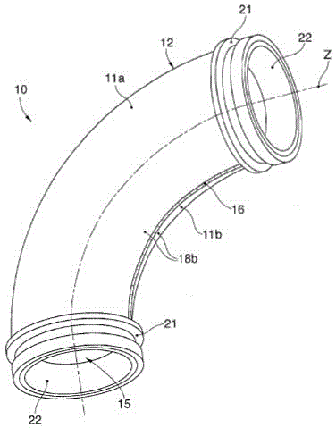
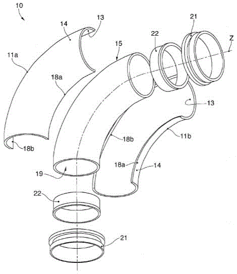
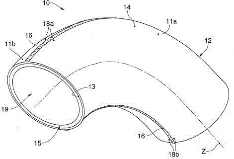
[0039] refer to figure 1 , in this embodiment, the curved pipe 10 for transporting abrasive material (eg concrete or the like) according to the present invention comprises two parts 11a and 11b (or shells). When connected and fixed to each other, the two parts 11a and 11b form a first outer part 12 having a tubular cross-section and having a curved extension along a bending axis Z (circle arc in this embodiment), a second inner A curved part or anti-wear insert 15 is provided within this first outer part 12 .

[0040] In particular, each part 11 a , 11 b has a cross section that is a corresponding portion of the tubular section of the first outer part 12 and extends longitudinally along the bending axis Z. The two parts 11a and 11b are connected to each other along respective longitudinal edges 18a, 18b by welding to obtain respective weld seams 16 .

[0041]The parts 11a and 11b can be welded by a welding method using oxyacetylene, electrodes, submerged arc welding (of the ...


PUM


Abstract

Method to make a curved tubular element comprising obtaining a first external curved tubular component (12), and a second internal curved component (15) made of a material with a greater resistance to wear than the first external curved tubular component (12), and having a cross section such as to cover at least part of the internal surface (13) of the first external curved tubular component (12). The method provides to make the first external curved tubular component (12) in at least two parts (11a, 11b) in which each of the parts has a cross section which is a respective portion of the complete tubular section of the first external curved tubular component (12); to bring the at least two parts (11a, 11b) near each other along respective connection edges (18a, 18b), disposing the second internal curved component (15) internally in contact with at least one of the two parts (11a, 11b); to weld the at least two parts (11a, 11b) to define the first external curved tubular component (12) and to enclose the second internal curved component (15) inside it.

Description

technical field [0001] The present invention relates to a method of making a curved pipe suitable for connection with other pipes (straight or curved) to form a conduit for conveying concrete or other abrasive material in a fluid state. In particular, the field of application of the invention is the construction industry, however it remains the case that the curved pipe according to the invention can also be used in other fields of industry. Background technique [0002] In the field of building construction it is known to use metal pipe fittings of the modular type. The pipes are connected to each other to obtain a pipeline that allows the concrete to be transported from the container (eg a concrete mixer truck) to the pouring area by means of pumping equipment. [0003] Depending on the nature of the area to be reached, pipes are connected to each other on each occasion. In particular, in order to allow a change of direction, straight pipes arranged in sequence are conne...

Claims


Application Information

Patent Timeline
Patent Type & Authority Applications(China)
IPC IPC(8): F16L43/00F16L57/06
CPCF16L9/14F16L57/06B65G53/523E04G21/04F16L43/00B65G2207/48F16L43/001F16L43/002
Inventor 法比奥·费雷多梅尼科·莫塔雷拉莫罗·马可·科特里尼
Owner CIFA
Features
  • R&D
  • Intellectual Property
  • Life Sciences
  • Materials
  • Tech Scout
  • Unparalleled Data Quality
  • Higher Quality Content
  • 60% Fewer Hallucinations
Learn More