Check patentability & draft patents in minutes with Patsnap Eureka AI!

Fixing device and image forming device

A technology of fixing belt and fixing roller, which is applied in the direction of electric recording process applying charge pattern, equipment for applying electric recording process of charge pattern, electric recording technique, etc. Slow, long warm-up time, etc.

Inactive Publication Date: 2016-06-08
KYOCERA DOCUMENT SOLUTIONS INC
View PDF3 Cites 0 Cited by
  • Summary
  • Abstract
  • Description
  • Claims
  • Application Information

AI Technical Summary

Problems solved by technology

However, in this method, there is a problem that the temperature rise of the fixing roller is slow and the warm-up time is long.
However, when the elastic layer of the fixing roller and the fixing belt are fixed with an adhesive, the heat generated on the fixing belt is dissipated into the adhesive layer.
Therefore, there will be such a problem that the warm-up time is long, and it takes time to heat the fixing roller from the standby temperature to the specified temperature.
In addition, this is also because the central portion of the fixing roller is constrained by the two ends of the fixing roller around it, and only the deformation in which the volume of the elastic layer is reduced due to the crushing of the cavity wall can be produced.

Method used


Image

  • Fixing device and image forming device
  • Fixing device and image forming device
  • Fixing device and image forming device

Examples


Embodiment Construction

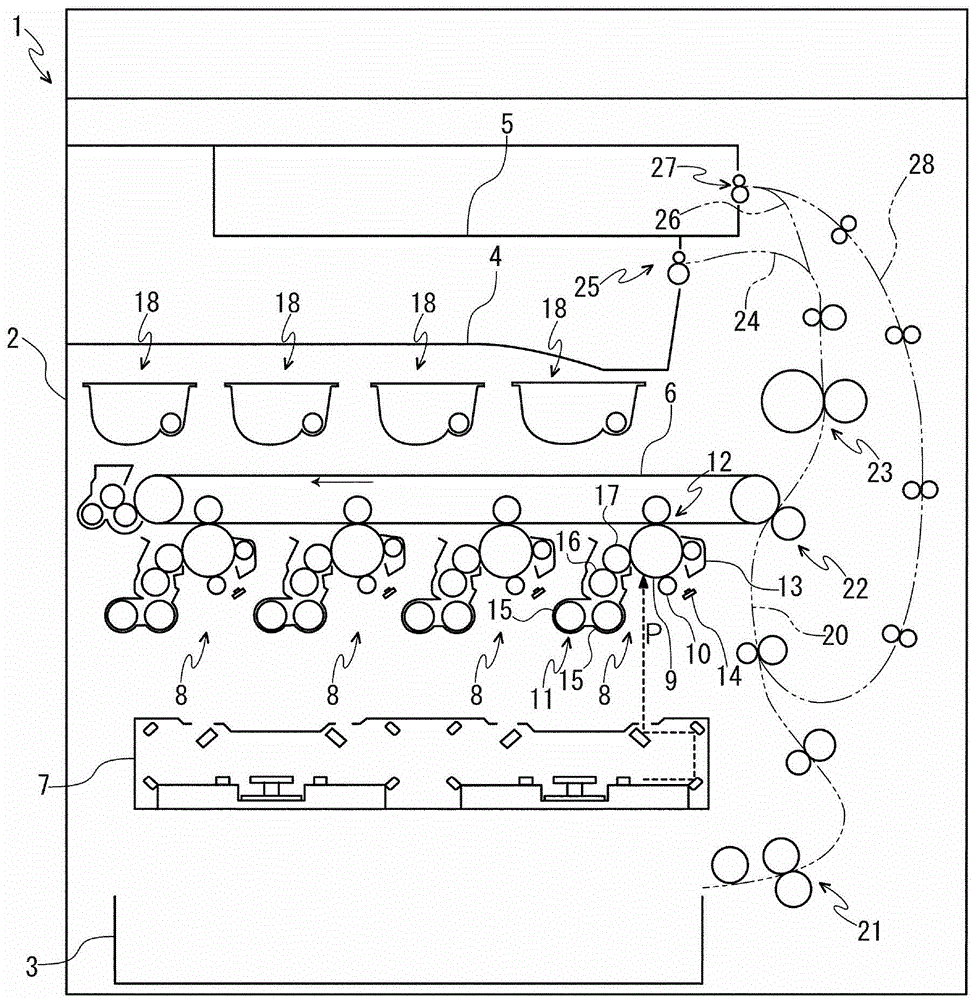
[0022] First, refer to figure 1 The overall configuration of the printer 1 (image forming apparatus) will be described. figure 1 It is a schematic configuration diagram showing a printer according to an embodiment of the present invention.

[0023] The printer 1 has a box-shaped printer main body 2. A paper feed cassette for storing paper as a recording body is provided on the lower part of the printer main body 2. A first paper output tray 4 is provided on the upper part of the printer main body 2. A second output tray 5 is provided above the paper tray 4 .

[0024] Inside the printer main body 2 , an intermediate transfer belt 6 (image carrier) is disposed between a plurality of rollers, and an exposure unit 7 constituted by a laser scanning unit (LSU) is disposed below the intermediate transfer belt 6 . Four image forming units 8 are provided on the lower side of the intermediate transfer belt 6 according to the color of toner (developer) (for example, four colors of ma...


PUM


Abstract

A fixing device includes a fixing belt, a heating source and a fixing roller. The fixing belt has a sheet passing part and a non-sheet passing part. The fixing roller includes an elastic layer including first and second elastic parts. The first elastic part is provided on an inner diameter side of the sheet passing part. The second elastic part is provided on an inner diameter side of the non-sheet passing part. A gap is formed between a part of the elastic layer and the fixing belt in a state where the fixing belt is not heated. The part of the elastic layer is in close contact with the fixing belt in a state where the fixing belt is heated. The first elastic part includes a small-diameter part having a smaller external diameter than a part with a maximum external diameter of the second elastic part.

Description

technical field [0001] The present invention relates to a fixing device for fixing a toner image on a recording medium such as paper or a film, and an image forming apparatus including the fixing device. Background technique [0002] Electrophotographic image forming apparatuses such as copiers and printers include a fixing device that fixes a toner image on a recording medium such as paper or film. As a method of fixing a toner image on a recording body, a heat fixing method in which a toner (developer) is melted by heating is generally used. In consideration of thermal efficiency and safety, the heat roller method is most widely used in a heat-fixing type fixing device like this. Here, the heat roller method refers to a method in which a fixing nip for fixing a toner image on a recording medium is formed by a fixing roller and a pressure roller. [0003] In the above-mentioned hot roller method, the following structure is often used, that is, the fixing roller is formed ...

Claims


Application Information

Patent Timeline
Patent Type & Authority Patents(China)
IPC IPC(8): G03G15/20G03G15/00
CPCG03G15/2053G03G15/2057
Inventor 南条让
Owner KYOCERA DOCUMENT SOLUTIONS INC
Features
  • R&D
  • Intellectual Property
  • Life Sciences
  • Materials
  • Tech Scout
  • Unparalleled Data Quality
  • Higher Quality Content
  • 60% Fewer Hallucinations
Learn More