dc/dc boost converter module and circuit
A technology for transforming modules and capacitors, which is applied in the electronic field and can solve problems such as inability to protect circuits
- Summary
- Abstract
- Description
- Claims
- Application Information
AI Technical Summary
Problems solved by technology
Method used
Image

Examples
Embodiment 1
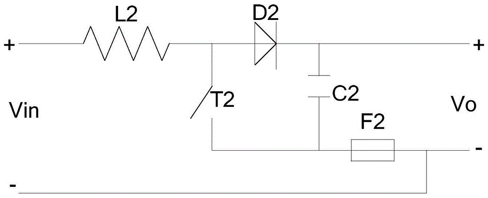
[0028] Such as image 3 As shown, the embodiment of the present invention proposes a DC / DC step-up conversion module, including an inductor L2, a switch tube T2, a diode D2, a capacitor C2 and a protection unit F2 (a fuse is used in this embodiment), and the positive pole of the input power Vin Connect to one end of the inductor L2, the other end of the inductor L2 is connected to the anode of the diode D2 and the positive pole of the switch tube T2, the cathode of the diode D2 is connected to the positive pole of the capacitor C2 and the positive pole of the output, and the negative pole of the switch tube T2 is connected to the negative pole of the capacitor C2 and the fuse One end of the fuse F2; the other end of the fuse F2 is connected to the negative pole of the input power supply Vin and the negative pole of the output. The switch tube T2 above can be a MOS tube or an IGBT. When the switch tube is a MOS tube, the positive pole is the D pole of the MOS tube, and the nega...
Embodiment 2
[0037] Such as Figure 8 As shown, this embodiment also proposes a DC / DC step-up conversion circuit, including at least two image 3 As shown in the DC / DC boost conversion module, the at least two DC / DC boost conversion modules are connected in parallel between the input power supply and the output, that is, the input ends of all DC / DC boost conversion modules are connected in parallel to the input Power supply, the output ends of all DC / DC step-up conversion modules are connected in parallel to the output. Four groups of photovoltaic modules PV1, PV2, PV3 and PV4 can be used to form the input voltage Vin after fusion of respective branch fuses. Take the nominal rated current of PV1, PV2, PV3 and PV4 as 8.0A, and the standard light short-circuit current of 9A as an example, choose fuses of 10-15A for F6 and F7. The maximum open-circuit voltage of PV1 and PV2 is 1000V, and the full-load MPPT voltage range is 450-750V. Assume that the output voltage Vo of the DC / DC boost conve...
Embodiment 3
[0040] Such as Figure 9 Shown is another embodiment of the present invention. The difference between this embodiment and Embodiment 1 is that the protection unit in Embodiment 1 uses automatic protection devices (such as fuses, fuses, etc.), while in this embodiment, switching devices T6 (such as contactors, thyristors SCR, IGBT, Mos tube, etc.), in Figure 9 The short-circuit failure of the switching tube T3 in the shown DC / DC voltage conversion module causes the fault to expand, which will further lead to overheating or smoke. The switching device T6 can be disconnected according to these fault phenomena, so as to realize the circuit protection function.
PUM
 Abstract
Description
Claims
Application Information
 - R&D
- Intellectual Property
- Life Sciences
- Materials
- Tech Scout
- Unparalleled Data Quality
- Higher Quality Content
- 60% Fewer Hallucinations
Browse by: Latest US Patents, China's latest patents, Technical Efficacy Thesaurus, Application Domain, Technology Topic, Popular Technical Reports.
© 2025 PatSnap. All rights reserved.Legal|Privacy policy|Modern Slavery Act Transparency Statement|Sitemap|About US| Contact US: help@patsnap.com