Lens and light emitting module adopting same

A technology of lenses and light-emitting components, which is applied in the direction of light sources, point light sources, and components of lighting devices, etc. It can solve problems such as small light-emitting angles, uneven light intensity, and the inability of light-emitting modules to achieve light-emitting effects, and achieve large light-emitting angles. , the effect of uniform light intensity

Inactive Publication Date: 2014-10-15
HONG FU JIN PRECISION IND (SHENZHEN) CO LTD +1
View PDF0 Cites 5 Cited by
  • Summary
  • Abstract
  • Description
  • Claims
  • Application Information

AI Technical Summary

Problems solved by technology

[0003] However, since a general lens only has one light-incident surface and one light-exit surface corresponding to the light-incidence surface, after the light emitted by the light-emitt

Method used


Image

  • Lens and light emitting module adopting same
  • Lens and light emitting module adopting same
  • Lens and light emitting module adopting same

Examples


Embodiment Construction

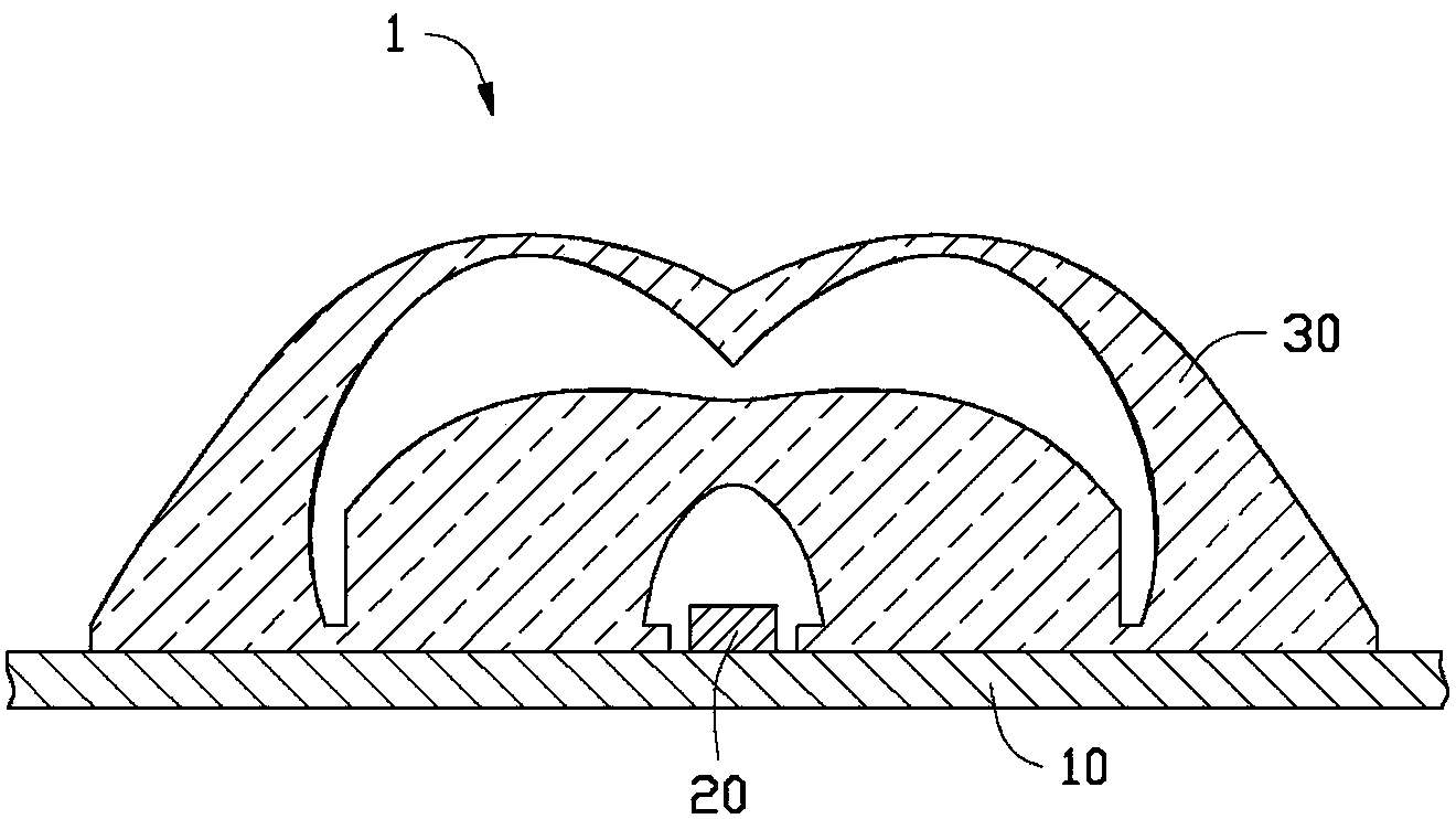
[0016] see figure 1 The light-emitting module 1 of the present invention includes a substrate 10 , a light-emitting element 20 disposed on the substrate 10 , and a lens 30 disposed on the substrate 10 and covering the light-emitting element 20 . The light emitted by the light emitting element 20 is diffused by the lens 30 and then emitted uniformly.

[0017] The substrate 10 is an insulating board, which can be made of ceramic (Ceramic), silicon (Si), sapphire (Sapphire), silicon carbide (SiC) and other materials.

[0018] In this embodiment, the light emitting element 20 is a light emitting diode. Certainly, in other embodiments, the light-emitting element 20 may also be other light-emitting bodies such as laser diodes.

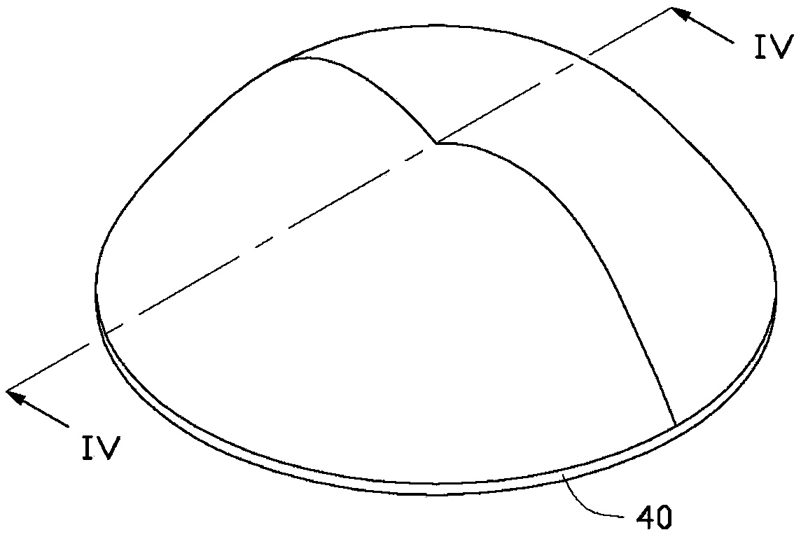
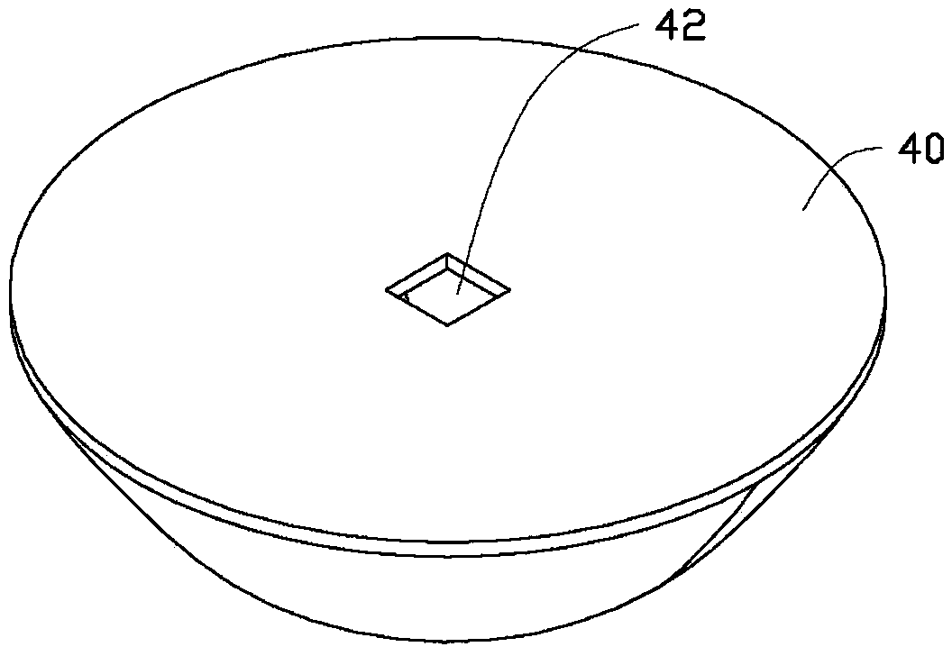
[0019] Please also see Figure 2 to Figure 4 , the lens 30 includes a base 40 , a first diverging portion 50 disposed on the base 40 , and a second diverging portion 60 disposed on the base 40 and accommodating the first diverging portion 50 inside.

[0...


PUM


Abstract

The invention discloses a lens. The lens is integrally formed and comprises a base, a first dispersing part and a second dispersing part, wherein the first dispersing part and the second dispersing part are arranged on the base, a containing hole is concavely formed in the second dispersing part, the first dispersing part is contained in the containing hole of the second dispersing part, the inner surface of the containing hole is in interval arrangement with the side surfaces and the top surface of the first dispersing part, and a containing groove which is used for containing a light emitting element is concavely formed in the first dispersing part. The invention also relates to a light emitting module adopting the lens.

Description

technical field [0001] The invention relates to a semiconductor structure, in particular to a lens and a light-emitting module using the lens. Background technique [0002] Existing LED modules generally include a substrate, a circuit structure disposed on the substrate, and LEDs disposed on the substrate and electrically connected to the circuit structure. In order to increase the light emitting angle of the light emitting diode, a lens is usually arranged above the light emitting diode. After the light emitted by the light-emitting diode is diffused by the lens, its light-emitting angle becomes larger. [0003] However, since a general lens only has one light-incident surface and one light-exit surface corresponding to the light-incidence surface, after the light emitted by the light-emitting diode is refracted by the lens, the light angle is still small, and the light intensity is still uneven, so that The entire lighting module cannot achieve a better lighting effect. ...

Claims


Application Information

Patent Timeline
IPC IPC(8): F21V5/04F21Y101/02
Inventor 王何立颖
Owner HONG FU JIN PRECISION IND (SHENZHEN) CO LTD
Why Eureka
Try Eureka