Power transmission line full waveform current differential protection judgment method and device

A transmission line and current differential technology, which is applied in the direction of emergency protection circuit devices, fault locations, electrical components, etc., can solve the problem of slow differential protection speed of transmission line sampling values, achieve good application prospects, and improve the effect of operating speed

Inactive Publication Date: 2014-11-05
HARBIN INST OF TECH +3
View PDF2 Cites 16 Cited by
  • Summary
  • Abstract
  • Description
  • Claims
  • Application Information

AI Technical Summary

Problems solved by technology

[0005] The purpose of the present invention is to solve the problem of slow differential protection speed for the sampling value of the transmission

Method used


Image

  • Power transmission line full waveform current differential protection judgment method and device
  • Power transmission line full waveform current differential protection judgment method and device
  • Power transmission line full waveform current differential protection judgment method and device

Examples


Example Embodiment

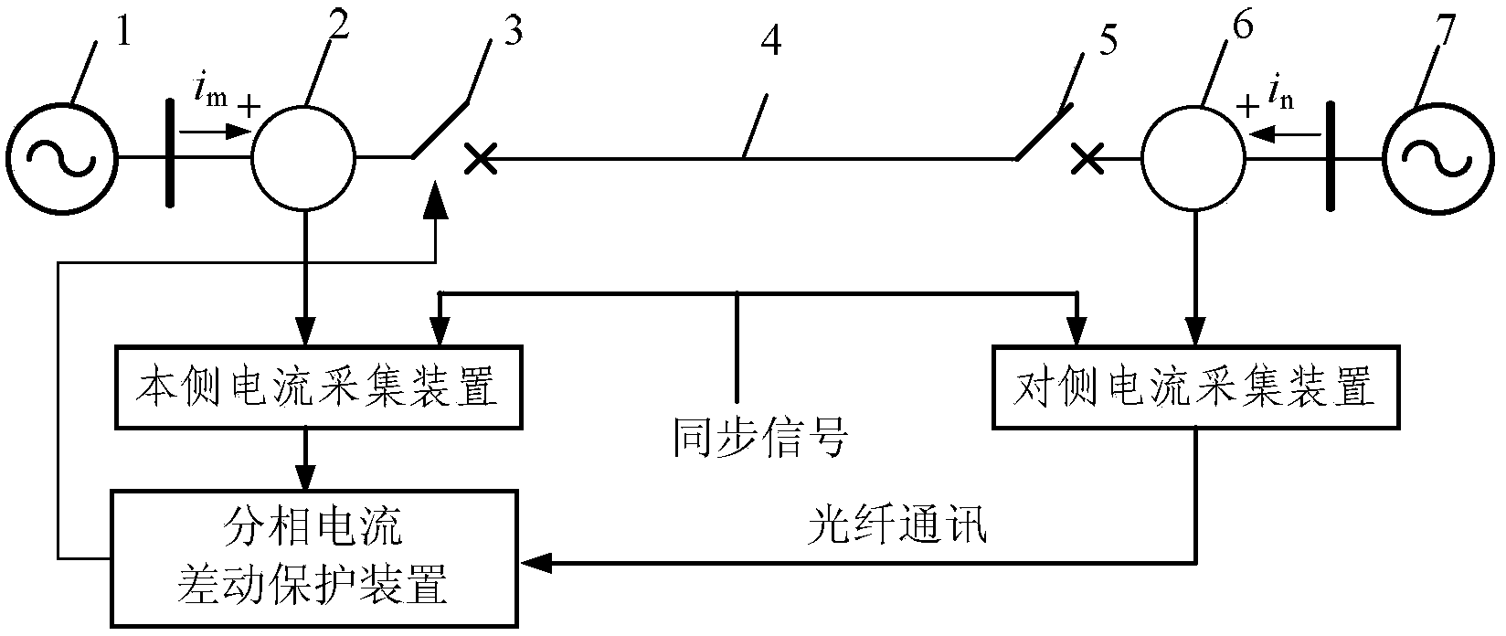
[0029] Specific implementation mode 1: Combination figure 1 with figure 2 To explain this embodiment, the method for determining the full-wave current differential protection of a transmission line described in this embodiment includes the following steps:

[0030] Step 1: Use an optical current transformer to synchronously sample the currents of each phase on both sides of the transmission line at a set sampling rate, and obtain the instantaneous value of current sampling on the local side and the instantaneous value of current sampling on the opposite side of each phase;

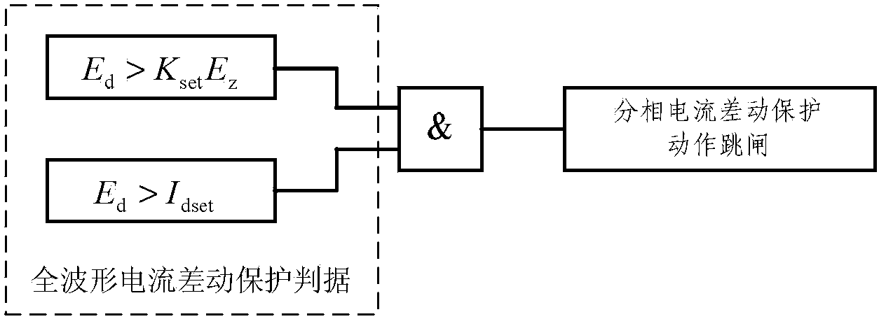
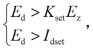
[0031] Step 2: Process the instantaneous value of the in-phase current sampling on the local side and the instantaneous value of the in-phase current sampling on the opposite side in step 1, respectively, and calculate the action amount E of the differential protection of each phase d And differential protection braking amount E z ;

[0032] Step 3: Use the operation amount E of each phase differential protecti...

Example Embodiment

[0037] Specific implementation manner 2: This implementation manner is a further limitation to the determination method of a transmission line full-wave current differential protection described in the specific implementation manner. The operation amount of the differential protection is The braking amount of the differential protection Where: i m , I n Sampling instantaneous value of the in-phase current on both sides of the line, t 1 To calculate the initial time, Δt is the integration time window.

Example Embodiment

[0038] Specific implementation mode three: combination figure 1 with figure 2 To explain this embodiment, what this embodiment describes is a transmission line full-wave current differential protection determination device, which includes a current acquisition device on the local side, a current acquisition device on the opposite side, and a split-phase current differential protection device;

[0039] The current acquisition device on the local side is a device used to collect the instantaneous value of each phase current on the current side according to the set sampling rate and synchronously with the current acquisition device on the opposite side;

[0040] Opposite-side current acquisition device, which is used to sample and collect the instantaneous value of each phase current on the opposite side according to the set sampling rate and synchronously with the local current acquisition device;

[0041] The split-phase current differential protection device includes the following ...


PUM


Abstract

The invention discloses a power transmission line full waveform current differential protection judgment method and device, and belongs to the technical field of power system relay protection. The method and device are used for solving the problem that differential protection performed on power transmission line sampling values is slow. An optical current transformer is used for synchronously sampling all the phases of current on the two sides of a power transmission line according to the set sampling rate, the sampling instantaneous value of each phase of current on the local side and the sampling instantaneous value of each phase of current on the opposite side, and the actuating quantity of differential protection of each phase and the braking quantity of differential protection of each phase are calculated; a current differential protection criterion is formed according to the obtained actuating quantity of differential protection of each phase and the braking quantity of differential protection of each phase, and whether a circuit breaker on the local side of the power transmission line acts or not is judged according to the current differential protection criterion (please see the criterion in the specifications). The power transmission line full waveform current differential protection judgment method and device are used for judging whether a fault happens in the power transmission line or not.

Description

technical field [0001] The invention belongs to the technical field of electric power system relay protection. Background technique [0002] The changes in the amount of information used in relay protection outline the development of relay protection principles: current protection uses current amplitude information; distance protection uses current, voltage amplitude and phase information; longitudinal protection uses double-terminal current amplitude and phase information , it can be seen that from the development of current protection to longitudinal protection, every breakthrough in the principle of relay protection is accompanied by an increase in the amount of protection information. However, the above-mentioned various protections are all based on power frequency. So far, the principle of relay protection is still mainly based on power frequency, that is, only the power frequency components in current and voltage are used. At present, the practical protection is basic...

Claims


Application Information

Patent Timeline
IPC IPC(8): H02H7/26G01R31/08
Inventor 张国庆于文斌郭志忠宋平黄华炜李传生申岩王贵忠
Owner HARBIN INST OF TECH
Why Eureka
Try Eureka