Check patentability & draft patents in minutes with Patsnap Eureka AI!

A Radiation Oriented Ring Forming Equipment

A technology of radiation orientation and forming equipment, which is applied in the field of hydraulic presses, can solve the problems of increasing the space volume of the device, low magnetic performance of the product, and low magnetic field strength, and achieve the effects of enhanced magnetic field strength, uniform radial arrangement of magnetic domains, and improved quality

Active Publication Date: 2016-08-31
NANTONG GUOYI FORGING MACHINE TOOL
View PDF9 Cites 0 Cited by
  • Summary
  • Abstract
  • Description
  • Claims
  • Application Information

AI Technical Summary

Problems solved by technology

[0004] The disadvantages of the molding device of the above-mentioned radiation orientation molding hydraulic press are: 1. The magnetic domains of the magnetic powder in the mold cavity are radially arranged by rotating the magnetizer to generate a radiation orientation magnetic field. In this way, the magnetic field intensity of the magnetic powder in the mold cavity Smaller, the magnetic properties of its products are low, and the magnetic field strength of its pressed magnet is 0.4-0.8T; 2. Through the magnetic conductor, the upper and lower orientation coils and the upper and lower magnetic conduction circuits, the magnetic domains of the magnetic powder in the mold cavity are radially arranged, and its structure Complicated and increases the space volume of the device

Method used


Image

  • A Radiation Oriented Ring Forming Equipment
  • A Radiation Oriented Ring Forming Equipment
  • A Radiation Oriented Ring Forming Equipment

Examples


Embodiment 1

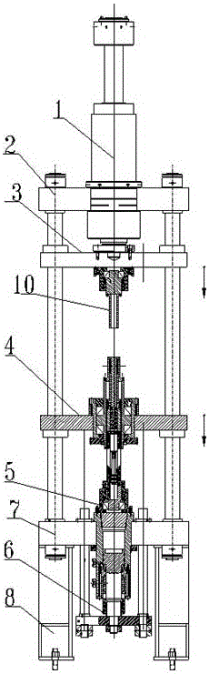
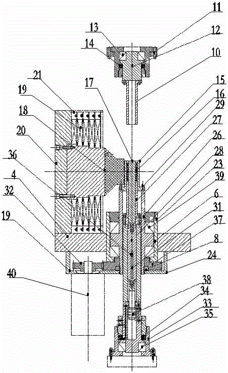
[0031] Such as figure 1 with figure 2 As shown, a radiation orientation ring forming equipment of the present invention includes a main cylinder 1, an upper beam 2, an upper slider 3, a female template 4, a central cylinder 5, a top cylinder 6, a workbench 7 and a support 8,

[0032] The above-mentioned upper beam 2, upper slider 3, female formwork 4, workbench 7 and support 8 are arranged sequentially from top to bottom. The four corners of the female template 4 are slidably matched with the guide post 9, and the bottom of the workbench 7 is supported by the support 8;

[0033] On the upper slider 3, an upper punch 10, an upper punch rotating assembly and an upper punch mounting seat 11 are installed, and the upper punch mounting seat 11 is fixed at the middle position of the upper sliding block 3, and the upper punch rotating assembly is composed of an upper punch connecting body 12, a bearing assembly A and bearing group mounting seat A, bearing group A thrust self-align...


PUM


Abstract

The invention relates to a radiation orientation forming equipment, which includes a main cylinder, an upper beam, an upper slider, a female template, a central cylinder, a top cylinder, a workbench and a support. The upper beam, upper slider, female template, and workbench The upper beam is connected and fixed with the workbench through the guide pillars at the four corners, the upper slider and the four corners of the female formwork are slidably matched with the guide pillars, and the bottom of the workbench is supported by the support; the upper slide The upper punch, the upper punch rotation assembly and the upper punch mounting seat are installed on the block, and the upper slider is driven by the master cylinder installed on the upper beam to move vertically along the axis of the guide column; the female template is installed with a female mold , lower punch, mandrel, radiation orientation electromagnet assembly and female mold rotation assembly; the top cylinder is used to drive the female template to move vertically along the axis of the guide post, and the central cylinder is used to drive the mandrel Make it move vertically along the axis of the guide post, and the mandrel is connected with the piston rod of the central cylinder. The invention has the advantages that the equipment has small volume and simple structure, and improves the magnetic performance and quality of the pressed magnet.

Description

technical field [0001] The present invention relates to a hydraulic press, in particular to a radiation oriented ring forming device. Background technique [0002] With the development and maturity of powder metallurgy technology, more and more materials are produced by powder metallurgy technology. It first presses the powder into a cake through a powder molding machine, and then sinters to make the final product. [0003] Our company's utility model patent with the patent number CN 103286980 A discloses a molding device for a radial orientation forming hydraulic press, which is mainly fixedly connected with the upper inner magnet and the upper die punch, and the inner ring of the upper die punch is fixedly connected with the inner ring of the upper die punch. Magnetic conductor, the top of the upper inner magnetic conductor is fixedly connected to the upper slider, and the outer ring of the upper inner magnetic conductor is connected with an upper orientation coil. It is...

Claims


Application Information

Patent Timeline
Patent Type & Authority Patents(China)
IPC IPC(8): B22F3/03B22F5/10H01F41/02
Inventor 颜国义
Owner NANTONG GUOYI FORGING MACHINE TOOL
Features
  • R&D
  • Intellectual Property
  • Life Sciences
  • Materials
  • Tech Scout
  • Unparalleled Data Quality
  • Higher Quality Content
  • 60% Fewer Hallucinations
Learn More