
PTFE pushing machine

A technology of PTFE and pusher, which is applied in the field of PTFE pusher, can solve the problems of unstable extrusion, fast and slow running speed, etc., and achieve the effect of large output torque and high working precision

Active Publication Date: 2014-11-19
温州神坤机械有限公司
View PDF6 Cites 0 Cited by
  • Summary
  • Abstract
  • Description
  • Claims
  • Application Information

AI Technical Summary

Problems solved by technology

However, the piston runs fast and slow during the extrusion stroke (extrusion material stage), resulting in unstable extrusion

Method used


Image

  • PTFE pushing machine
  • PTFE pushing machine
  • PTFE pushing machine

Examples


Embodiment Construction

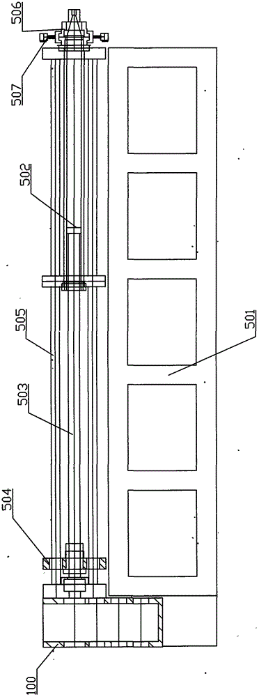
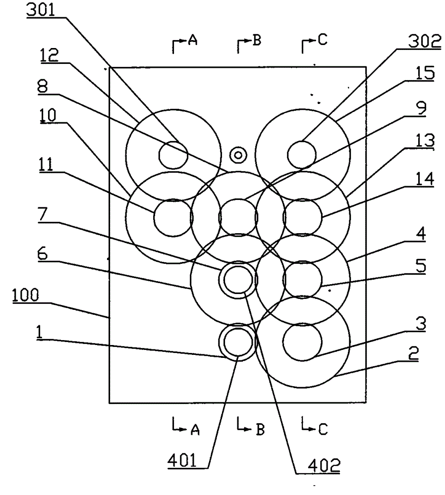
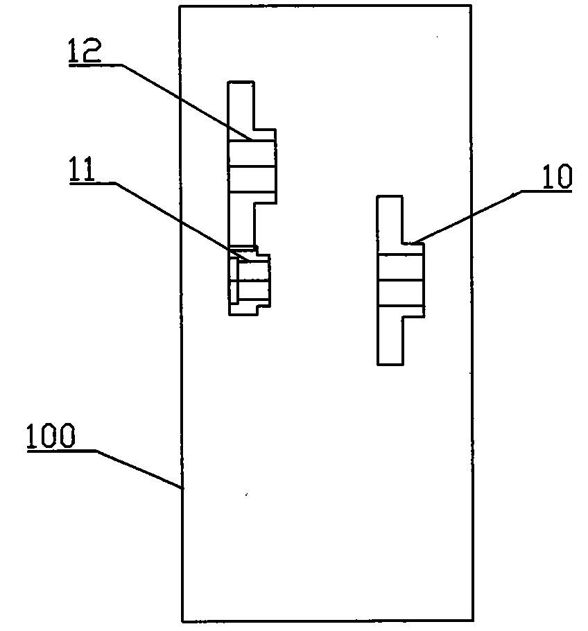
[0025] Below in conjunction with accompanying drawing, the present invention will be further described with specific embodiment, see Figure 1-Figure 4 ;

[0026] The PTFE pushing machine given in this embodiment includes a main body of a horizontal pushing machine and a double-input reducer. Plate 504, polished rod 505, mold 506 and hydraulic clamping device 507, the cylinder is installed on the machine base 501, the piston 502 is arranged in the cylinder and forms a sealing fit with the cylinder, and the mold 506 is sealed by the hydraulic clamping device 507. Assembled on the front end of the cylinder; the screw rod 503 is rotatably connected with respect to the machine base 501, and the nut on the moving push plate 504 matches the screw rod, and the nut and the screw rod form a screw nut pair, through the rotation of the screw rod Make the moving push plate move axially along the screw rod. The moving push plate 504 forms a sliding connection with the polished rod 505 . ...


PUM


Abstract

The invention discloses a PTFE pushing machine capable of slowly progressing and quickly reversing. The PTFE pushing machine comprises a speed reducer and a main pushing machine body, wherein the speed reducer is characterized in that a first input shaft is rotatably mounted on a box body; the output end of a first power source is connected with the first input shaft in a transmission manner; a second input shaft is rotatably mounted on the box body; the output end of a second power source is connected with the second input shaft in a transmission manner; the first input shaft is connected with the second input shaft through a first gear speed reducing mechanism in a transmission manner on the second input shaft; the first gear speed reducing mechanism is connected with the second input shaft in a clutching manner by means of an electromagnetic clutch, so that a driving torque drives from the first input shaft to the second input shaft in one direction; the second input shaft is connected with a first output shaft through a second gear speed reducing mechanism in a transmission manner and is connected with a second output shaft through a third gear speed reducing mechanism in a transmission manner; the first output shaft and the second output shaft are rotatably mounted on the box body; and each of the first output shaft and the second output shaft is connected with one screw rod in a transmission manner.

Description

technical field [0001] The invention belongs to the technical field of PTFE material molding, and in particular relates to a PTFE pushing machine. Background technique [0002] At present, PTFE pushers are mainly used in the following fields: for the production of PTFE hollow tubes; for the production of PTFE high-temperature wires and high-frequency coaxial cables; for the production of PTFE hollow fiber membranes. [0003] PTFE extrusion machine is divided into vertical PTFE extrusion machine and horizontal PTFE extrusion machine. At present, the domestically produced PTFE pusher is a vertical PTFE pusher, which uses a worm gear reduction mechanism to drive the screw to rotate. The production of the PTFE pusher with this structure is inconvenient, and the wear of the worm gear is relatively large, and the service life is not long. [0004] The worm gear reduction mechanism cannot be applied to the horizontal PTFE extrusion machine. For this reason, a horizontal PTFE pus...

Claims


Application Information

Patent Timeline
IPC IPC(8): B29C47/08B29C47/54
CPCB29C48/2526B29C48/475B29K2027/18
Inventor 吴波
Owner 温州神坤机械有限公司
Features
  • Generate Ideas
  • Intellectual Property
  • Life Sciences
  • Materials
  • Tech Scout
  • Unparalleled Data Quality
  • Higher Quality Content
  • 60% Fewer Hallucinations
Learn More