Supercharge Your Innovation With Domain-Expert AI Agents!

Optical module identification method and port extender

A technology for port expansion equipment and identification methods, which is applied in the field of methods and port expansion equipment, and can solve the problems of increasing the complexity of the power-on startup program, reducing stability, and high difficulty

Active Publication Date: 2014-11-19
NEW H3C TECH CO LTD
View PDF6 Cites 9 Cited by
  • Summary
  • Abstract
  • Description
  • Claims
  • Application Information

AI Technical Summary

Problems solved by technology

At present, there is no general I2C read-write module interface in the power-on and start-up program of PE equipment.
If a unified I2C access unit is developed in the power-on startup program, not only is it very difficult, but it will greatly increase the complexity of the power-on startup program and reduce stability

Method used


Image

  • Optical module identification method and port extender
  • Optical module identification method and port extender
  • Optical module identification method and port extender

Examples


Embodiment Construction

[0032] The present invention will be described in detail below in conjunction with specific embodiments shown in the accompanying drawings. However, these embodiments do not limit the present invention, and any structural, method, or functional changes made by those skilled in the art according to these embodiments are included in the protection scope of the present invention.

[0033] Those skilled in the art should understand that the block diagrams presented in the accompanying drawings represent schematic illustrations of structures or circuits for implementing the present invention. Similarly, it should be understood that any flowcharts and the like presented in the drawings of the specification represent various processes that can actually be executed by various computers or processors, regardless of whether such computers or processors are explicitly shown in the drawings.

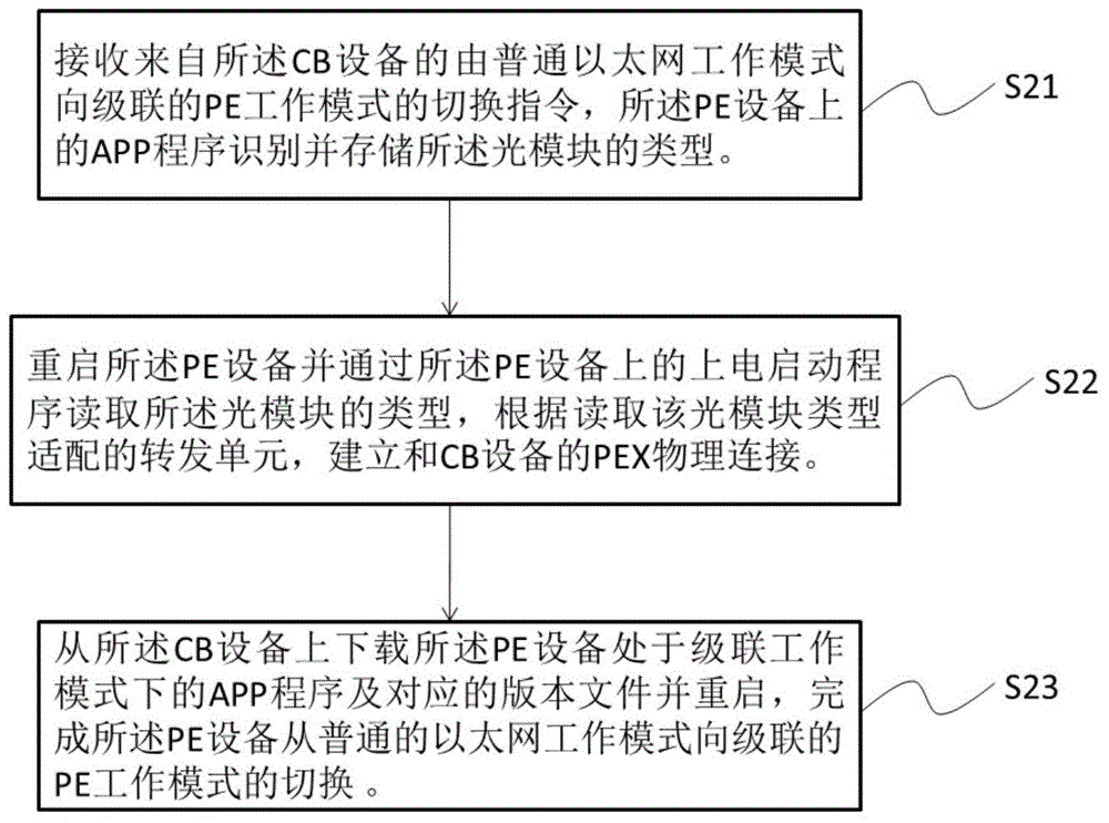
[0034] refer to figure 1 , the optical module identification method provided by the present inv...


PUM


Abstract

The invention provides an optical module identification method in a Bootware stage in a longitudinal stacking system. An optical module is arranged in a PE (Port Extender), and connected with a CB (Control Bridge) via a physical link. The method comprises the steps that: a switchover instruction from a common Ethernet operation mode to a cascaded PE operation mode is received from the CB; an APP (Application) on the PE identifies and stores a type of the optical module; the PE is restarted; the type of the optical module is read via a power-on startup program on the PE; a forward unit is adapted according to the read type of the optical module; a PEX physical connection with the CB is established; then, an APP in a cascade operation mode of the PE and a corresponding version file are downloaded from the CB; the CB is restarted; and the switchover of the PE from the common Ethernet operation mode to the cascaded PE operation mode is accomplished.

Description

technical field [0001] The invention relates to the communication field, in particular to a method for identifying an optical module at the Bootware stage after a port expansion device in a vertical stacking system is switched from a normal Ethernet working mode to a cascaded Ethernet working mode and the port expansion device. Background technique [0002] A development trend of the current data center technology is to realize the port expansion of CB equipment (Control Bridge, control bridge equipment) by establishing a vertical stacking system, so as to achieve single and flat management and reduce network layers. In the process of building a vertical stacking system, in order to further realize intelligence, PE equipment (Port Extender, port expansion equipment) needs to be able to automatically switch from the normal Ethernet working mode to the cascaded Ethernet working mode after connecting to the CB equipment , that is, to realize the plug-and-play function of the PE...

Claims


Application Information

Patent Timeline
Patent Type & Authority Applications(China)
IPC IPC(8): H04L12/28G06F9/445
Inventor 周孟韬祁正林薛聪
Owner NEW H3C TECH CO LTD
Features
  • R&D
  • Intellectual Property
  • Life Sciences
  • Materials
  • Tech Scout
  • Unparalleled Data Quality
  • Higher Quality Content
  • 60% Fewer Hallucinations
Learn More