Supercharge Your Innovation With Domain-Expert AI Agents!

A housing for a device

A technology of housing and clamping device, which is applied in the direction of sealed housing, electrical equipment housing/cabinet/drawer, electrical components, etc., can solve the problem of time-consuming manufacturing process

Inactive Publication Date: 2014-11-26
BERGE SOLUTIONS
View PDF2 Cites 0 Cited by
  • Summary
  • Abstract
  • Description
  • Claims
  • Application Information

AI Technical Summary

Problems solved by technology

However, in order to accommodate components protruding from the housing, such as pressure switches ("buttons") or contacts, the casting must be manufactured in several steps
The manufacturing process is time-consuming because the polymer must cure between steps

Method used


Image

  • A housing for a device
  • A housing for a device
  • A housing for a device

Examples


Embodiment Construction

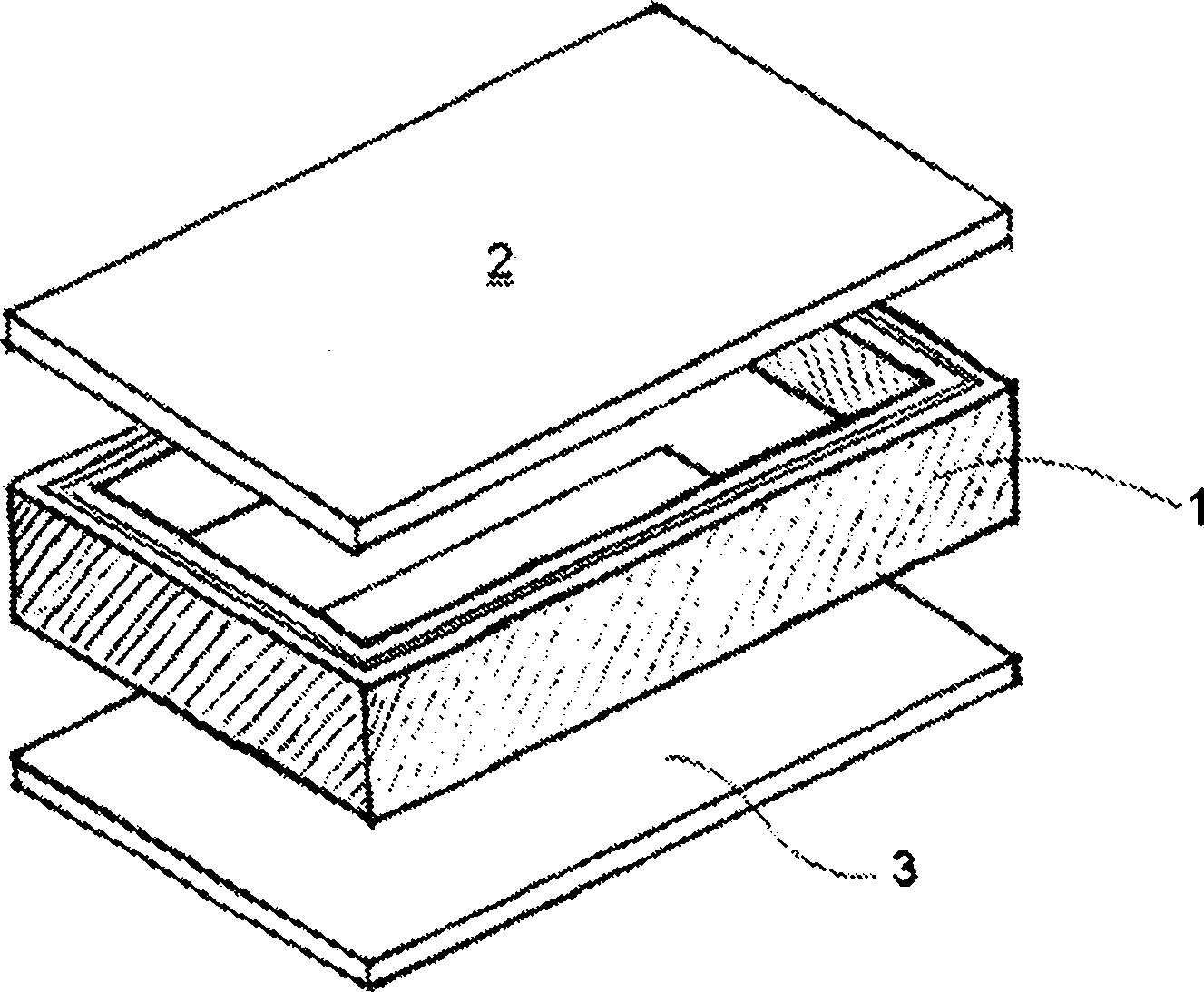
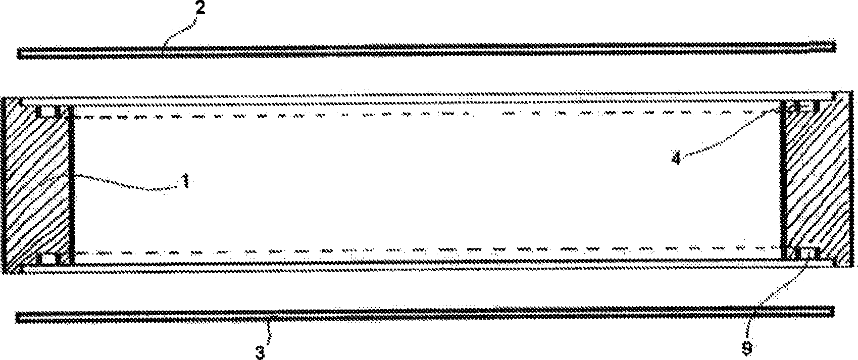
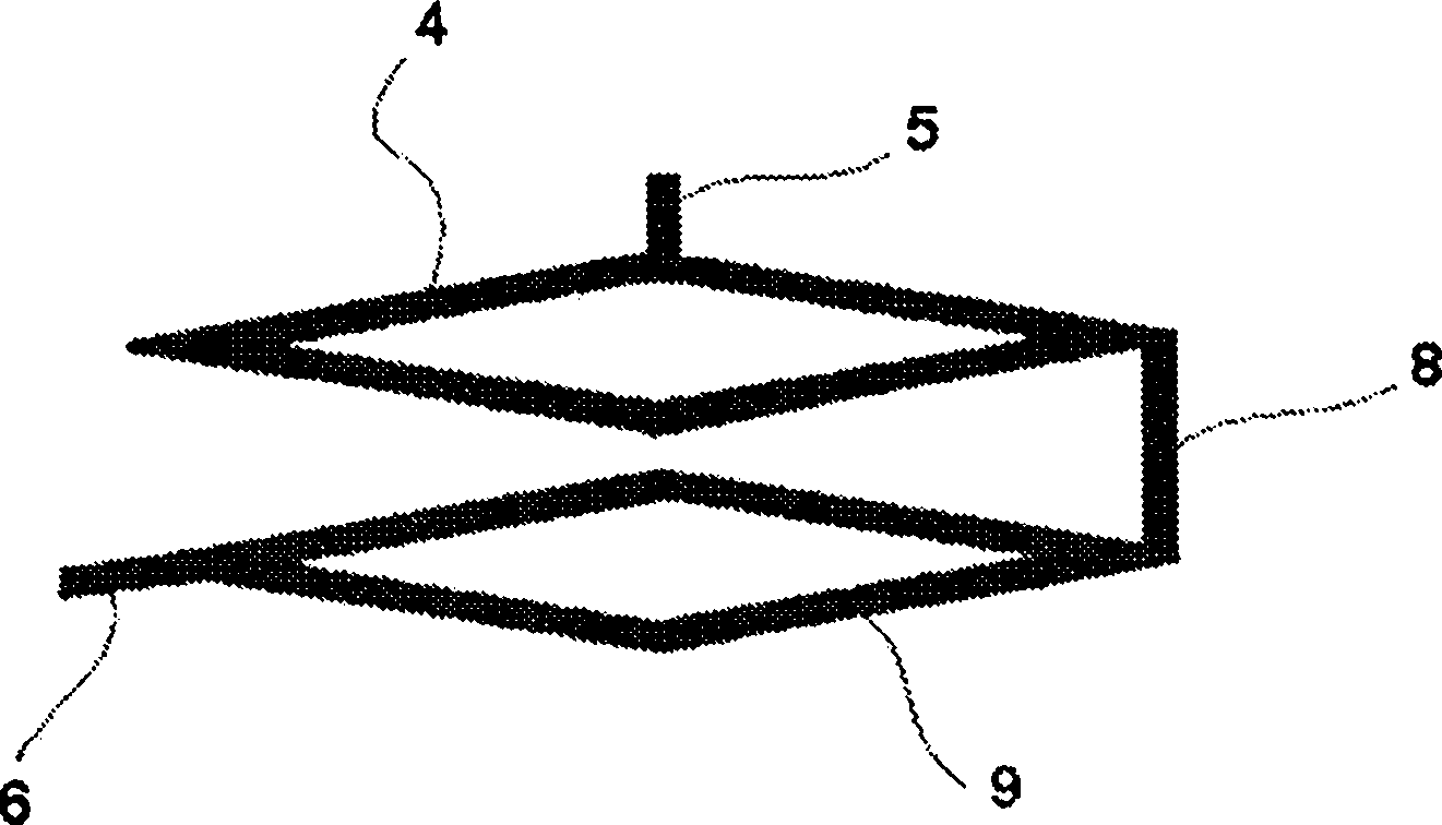
[0011] figure 1 An embodiment of the invention is illustrated in which several parts are assembled into a rectangular housing for an electronic device. The housing comprises a rectangular frame 1 closed by a top cover 2 and a bottom cover 3 . In the top and bottom surfaces of the frame 1 there are grooves 4 for holding gaskets. The grooves can be formed when casting the frame or by rolling. When the cover is fitted to the frame, these grooves will form closed segment channels as figure 2 a, b shown. The groove in the top surface will form the first gasket channel 4 , while the groove in the bottom surface will form the second gasket channel 9 . The first gasket channel 4 is connected to the inlet channel 5 . The transfer channel 8 interconnects the first gasket channel 4 and the second gasket channel 9 . The second gasket channel 9 is connected to the outlet channel 6 .

[0012] These channels will form a continuous flow loop from inlet to outlet, as image 3 shown. ...


PUM


Abstract

There is disclosed a housing for electronic devices. The housing is assembled from several components (if 2). The components form a continuous closed section gasket channel (4, 9) there between. A suitable fluid is injected into said channel to form a gasket between the components.

Description

technical field [0001] The present invention relates to an enclosure for encapsulating precision equipment against harsh environments. Background technique [0002] Sometimes electronic devices are installed in harsh environments such as production plants, drilling decks of offshore platforms or on board ships. Special enclosures are required for these devices to protect against ingress of water or explosive atmospheres. The devices in question may be control panels, computers or display units. Typically, this is standard equipment such as a personal computer, which is installed in a specific enclosure with thick walls and a lid sealed with a rubber gasket. Such packages are very bulky and expensive. [0003] The present inventor has made a computer for use on the bridge of a ship. This computer is used to present navigational information to the navigator or helmsman. The current solution is to cast computer components as compact blocks using suitable polymers. However...

Claims


Application Information

Patent Timeline
Patent Type & Authority Applications(China)
IPC IPC(8): H05K5/06
CPCH05K5/062
Inventor T·B·梅瓦特内
Owner BERGE SOLUTIONS
Features
  • R&D
  • Intellectual Property
  • Life Sciences
  • Materials
  • Tech Scout
  • Unparalleled Data Quality
  • Higher Quality Content
  • 60% Fewer Hallucinations
Learn More