Supercharge Your Innovation With Domain-Expert AI Agents!

Power conversion apparatus

A power conversion device and electric power technology, applied in the direction of output power conversion device, printed circuit stress/deformation reduction, printed circuit, etc., can solve the problems of reduced durability and reliability of power conversion device

Inactive Publication Date: 2014-12-10
NISSAN MOTOR CO LTD
View PDF7 Cites 5 Cited by
  • Summary
  • Abstract
  • Description
  • Claims
  • Application Information

AI Technical Summary

Problems solved by technology

There is a problem that the durability reliability of the power conversion device decreases due to the stress

Method used


Image

  • Power conversion apparatus
  • Power conversion apparatus
  • Power conversion apparatus

Examples


Embodiment Construction

[0038] Hereinafter, embodiments of the present invention will be described with reference to the drawings.

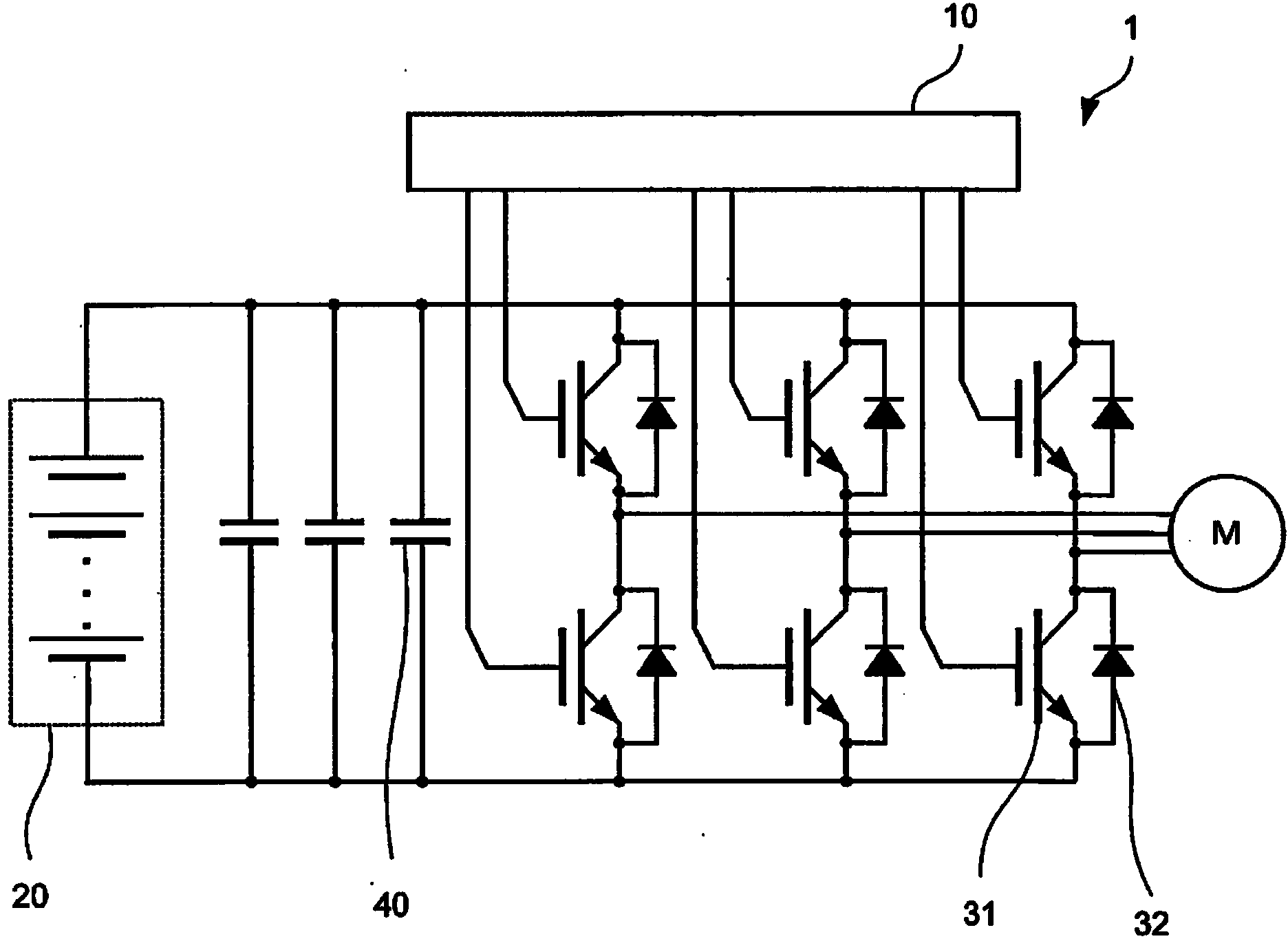
[0039] figure 1 It is an explanatory diagram of the drive system 1 according to the first embodiment of the present invention.

[0040] The drive system 1 is composed of a power conversion device 50 , a battery 20 , and a drive motor M. As shown in FIG. The power conversion device 50 includes a control circuit 10 , a power semiconductor 31 , a diode 32 , a smoothing capacitor 40 , and the like, and the output of the power semiconductor 31 is controlled by the control circuit 10 to control the drive motor M.

[0041] The battery 20 supplies electric power to the electric motor M for driving, and stores regenerative electric power of the electric motor M for driving. The battery 20 is constituted as a battery module in which a plurality of secondary batteries such as lead batteries, nickel-metal hydride batteries, or lithium-ion batteries are connected in series or in p...


PUM


Abstract

This power conversion apparatus is provided with a power module, a base section that is provided with a cooler, a second substrate, a first bus bar, a second bus bar, a smoothing capacitor, and a first substrate. The power module is placed on the upper surface of the base section, and above the power module, the first bus bar, the smoothing capacitor, and the first substrate are provided by being sequentially laminated. The second substrate is provided in the upright direction with respect to the base section, and is fixed to the power module and the first substrate.

Description

technical field [0001] The present invention relates to a power conversion device that converts electric power with a semiconductor element. Background technique [0002] A power conversion device used for inverter control of a motor or the like is configured by including power semiconductors such as switching elements and a control circuit for controlling the operation of the power semiconductor device. Since power semiconductors often generate heat, it is necessary to configure the control circuit so that it is not affected by heat. [0003] As such a power conversion device, JP4609504B discloses that a second circuit board on which circuit components for controlling power semiconductor elements are mounted is arranged in a vertical direction relative to a first circuit board on which power semiconductor elements are mounted, and one end of the circuit board is connected to The first circuit substrate is electrically bonded. [0004] In the power conversion device config...

Claims


Application Information

Patent Timeline
Patent Type & Authority Applications(China)
IPC IPC(8): H02M7/00H02P27/06
CPCH02M7/003H05K7/209H02M7/537H05K1/0271H05K1/181H05K2201/10015H05K2201/10037H05K2201/10151H05K2201/10174H05K2201/10272
Inventor 中山裕介长井纯之
Owner NISSAN MOTOR CO LTD
Features
  • R&D
  • Intellectual Property
  • Life Sciences
  • Materials
  • Tech Scout
  • Unparalleled Data Quality
  • Higher Quality Content
  • 60% Fewer Hallucinations
Learn More