Supercharge Your Innovation With Domain-Expert AI Agents!

laser marking machine

A laser marking machine and laser transmitter technology, applied in the field of laser marking machines, can solve problems such as inability to precisely control processing accuracy, reduce work efficiency, and inability to carry out processing, so as to isolate the laser irradiation point from workers and reduce work-related injuries. Accidents, the effect of improving processing efficiency

Active Publication Date: 2015-11-25
TAIZHOU CHENGGUANG LASER EQUIP
View PDF8 Cites 1 Cited by
  • Summary
  • Abstract
  • Description
  • Claims
  • Application Information

AI Technical Summary

Problems solved by technology

[0002] Laser marking machines are widely used in engraving on objects. People place the workpiece on the workbench. When a workpiece is processed, it needs to be removed. As a result, when people take the workpiece by mistake, the laser will be shot on the hand, resulting in safety accidents. , and people cannot process when they take the workpiece, which greatly reduces the work efficiency, and the direct use of conveyor belts in the market leads to the inability to accurately control the processing accuracy

Method used


Image

  • laser marking machine
  • laser marking machine
  • laser marking machine

Examples


Embodiment Construction

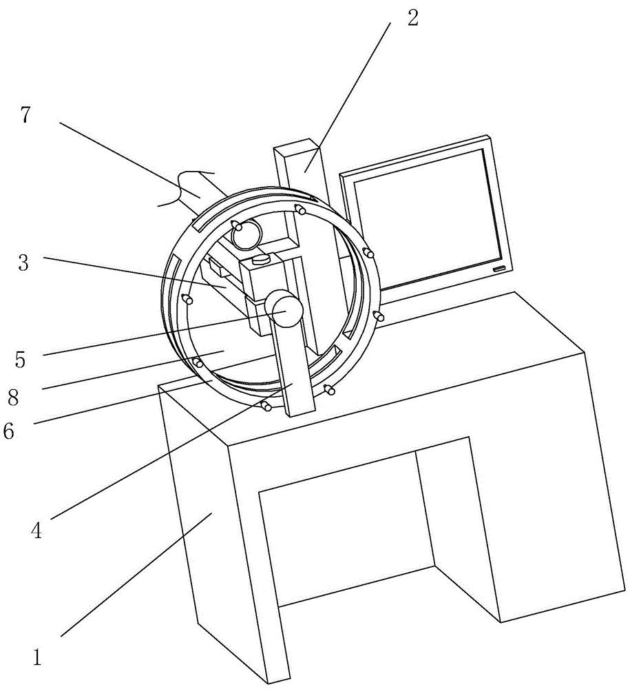
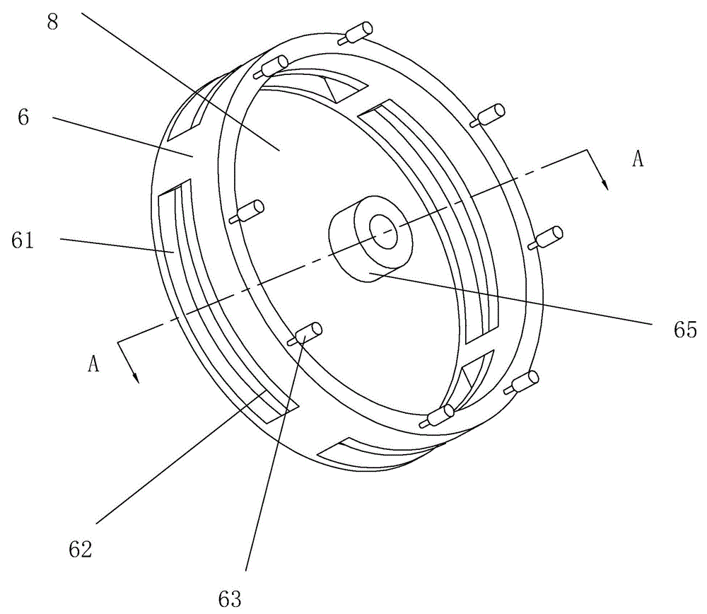
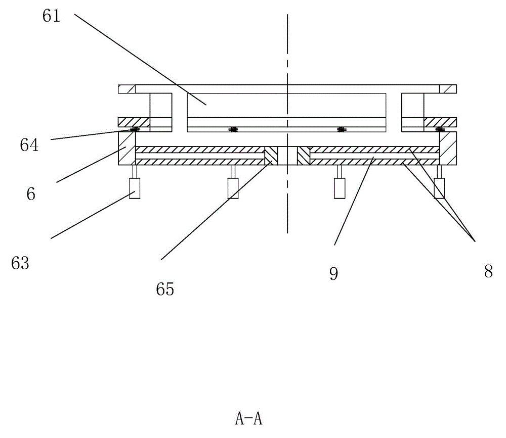
[0014] refer to Figure 1 to Figure 3 The embodiment of the laser marking machine of the present invention will be further described.

[0015] A laser marking machine, comprising a workbench 1 and a fixed column 2, the fixed column 2 is vertically fixed on the top of the workbench 1, and two laser emitters 3 are fixedly connected to the fixed column 2, and the two laser emitters The emission port of the device 3 is oppositely set, the laser emission direction is perpendicular to the workbench 1, the top of the workbench 1 is fixedly connected with a pillar 4, the pillar 4 is fixedly connected with a servo motor 5, and the servo motor 5 is fixedly connected There is a fixed disk 8, and the fixed disk 8 has at least 4 fixed fixtures in a circumferential array near the laser emitter 3. The fixed fixtures are all set opposite to the laser emitter 3, and the workpiece is clamped on the fixed fixture. The motor 5 rotates at a fixed angle so that the two unprocessed workpieces close...


PUM


Abstract

The invention discloses a laser marking machine. The laser marking machine is characterized by comprising a workbench and a fixing column; the fixing column is vertically fixed at the top of the workbench; the fixing column is fixedly connected with two laser transmitters; transmitting openings of the two laser transmitters are formed oppositely; the laser transmitting direction is perpendicular to the workbench; the top of the workbench is fixedly connected with a strut which is fixedly connected with a servo motor; the servo motor is fixedly connected with a fixing disk; at least four fixing clamps are circularly arrayed on one side of the fixing disk, wherein the side of the fixing disk is close to the laser transmitters; the fixing clamps and the laser transmitters are arranged oppositely; workpieces are clamped on every fixing clamp and two of the workpieces are simultaneously machined through the rotation of the fixing disk. Accordingly, the laser marking machine is safe in operation, high in machining efficiency and high in accuracy.

Description

technical field [0001] The invention relates to a laser marking machine. Background technique [0002] Laser marking machines are widely used in engraving on objects. People place the workpiece on the workbench. When a workpiece is processed, it needs to be removed. As a result, when people take the workpiece by mistake, the laser will be shot on the hand, resulting in safety accidents. , and people cannot process when they take the workpiece, which greatly reduces the work efficiency, and when the conveyor belt is directly used in the market for transportation, it is impossible to accurately control the processing accuracy. Contents of the invention [0003] In view of the deficiencies in the prior art, the object of the present invention is to provide a laser marking machine with safe operation, high processing efficiency and high precision. [0004] In order to achieve the above object, the present invention provides the following technical solutions: a laser marking m...

Claims


Application Information

Patent Timeline
Patent Type & Authority Patents(China)
IPC IPC(8): B23K26/36B23K26/362B23K26/70
Inventor 林中良
Owner TAIZHOU CHENGGUANG LASER EQUIP
Features
  • R&D
  • Intellectual Property
  • Life Sciences
  • Materials
  • Tech Scout
  • Unparalleled Data Quality
  • Higher Quality Content
  • 60% Fewer Hallucinations
Learn More