
Ascending and descending controllable deceleration device for road vehicle height limitation

A technology for road vehicles and deceleration devices, which is applied to transmission devices, components with teeth, belts/chains/gears, etc., to achieve the effect of improving the stability of use

Active Publication Date: 2015-02-04
ANHUI SUN CREATE ELECTRONICS
View PDF5 Cites 0 Cited by
  • Summary
  • Abstract
  • Description
  • Claims
  • Application Information

AI Technical Summary

Problems solved by technology

[0005] In order to solve the problems of accurate transmission ratio, good technical performance, manual operability, equipment interchangeability and universal type, etc., the present invention provides a lift controllable deceleration device for road vehicle height limit

Method used


Image

  • Ascending and descending controllable deceleration device for road vehicle height limitation
  • Ascending and descending controllable deceleration device for road vehicle height limitation
  • Ascending and descending controllable deceleration device for road vehicle height limitation

Examples


Embodiment

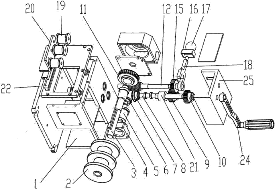
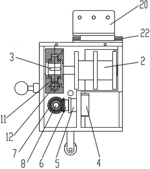
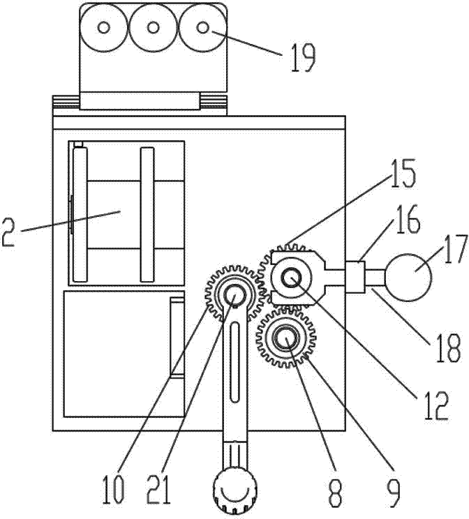
[0020] see figure 1 A lifting controllable deceleration device for height limitation of road vehicles includes a body 1 and a transmission mechanism located in the body 1 . The transmission mechanism includes a first transmission shaft 3, a second transmission shaft 8, a third transmission shaft 21 and a fourth transmission shaft 5; one end of the first transmission shaft 3 is fixedly mounted with a cable pulley 2, and the other end is fixedly mounted with a worm wheel 11; see figure 2 The worm 12 cooperating with the worm wheel 11 is installed under the worm wheel 11, the other side of the worm wheel 11 is a polished rod, and a transition gear 15 is fixedly installed on the polished rod, and the worm wheel 11 is perpendicular to the first transmission shaft 3. A fourth transmission shaft 5 is arranged parallel to the bottom of the first transmission shaft 3 , an input base 4 is fixedly mounted on one end of the fourth transmission shaft 5 , and a first bevel gear 6 is fixed...


PUM


Abstract

The invention discloses an ascending and descending controllable deceleration device for road vehicle height limitation. The ascending and descending controllable deceleration device comprises a machine body and a transmission mechanism positioned in the machine body, wherein the transmission mechanism comprises a steel rope wheel, a worm wheel and worm rod transmission pair, a bevel gear transmission pair, a reversing transmission transition gear, a first gear and a second gear. The torque input by an external motor is used as the torque for active mechanical operation, through the accurate transmission ratio of the worm wheel and a worm rod, the gear engaging force is transmitted onto a worm rod, and then, through the worm wheel transmission, the output torque is conveyed onto the steel rope wheel, so that the steel cable wheel does positive and reverse operation along with the steering of the worm wheel, so the steel cable wheel is enabled to obtain a greater torque, and the height limiting ascending and descending deceleration control is realized. The ascending and descending controllable deceleration device has the advantages that the problems can be solved to realize the accurate transmission ratio, good technical performance, good manual operability, equipment interchangeability, universality and the like, and the design requirement of road vehicle height limitation is realized to the maximum degree.

Description

technical field [0001] The invention belongs to the technical field of mechanical deceleration, and in particular relates to a height-limiting lift controllable deceleration device for road vehicles. Background technique [0002] At present, the height limiting devices for road vehicles in the prior art generally adopt the structural design of tubular structure and hydraulic system, which meets the technical requirements of vehicle height limit to a certain extent; but with the high standard of height limiting technical conditions, in the intelligent In terms of humanization, such as customization and easy operation, the above-mentioned structural design defects are also becoming more and more prominent; [0003] 1. When the height limiting device adopts a tubular structure design, it needs to be installed on the upper part of the road gantry pole. (1) When a power failure occurs in an emergency, the tubular structure design cannot be operated by hand at the front end, which...

Claims


Application Information

Patent Timeline
IPC IPC(8): F16H37/12
CPCF16H37/12F16H2702/00
Inventor 徐戚丁镇吴亚峰冉艳李绍甫林家骐李永睿李园徐静姬晓波
Owner ANHUI SUN CREATE ELECTRONICS
Learn More