Plasma comb and manufacturing method thereof
A plasma and comb technology, applied in hair combs, clothing, hairdressing equipment, etc., can solve problems such as damage to the body's hematopoietic system, loss of hair scales, human health hazards, etc., to shorten the required time and improve hair quality. , the effect of improving hydrophilicity
- Summary
- Abstract
- Description
- Claims
- Application Information
AI Technical Summary
Problems solved by technology
Method used
Image

Examples
Embodiment Construction
[0033] Below in conjunction with accompanying drawing, further elaborate the present invention. It should be understood that these examples are only used to illustrate the present invention and are not intended to limit the scope of the present invention. In addition, it should be understood that after reading the teachings of the present invention, those skilled in the art can make various changes or modifications to the present invention, and these equivalent forms also fall within the scope defined by the appended claims of the present application.
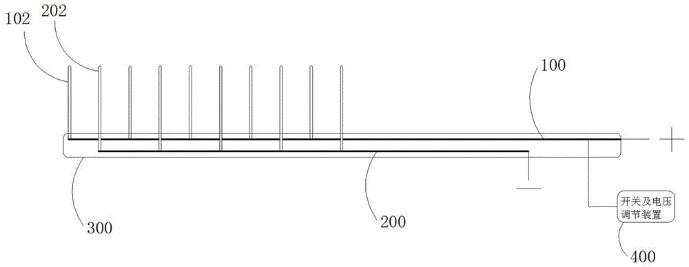
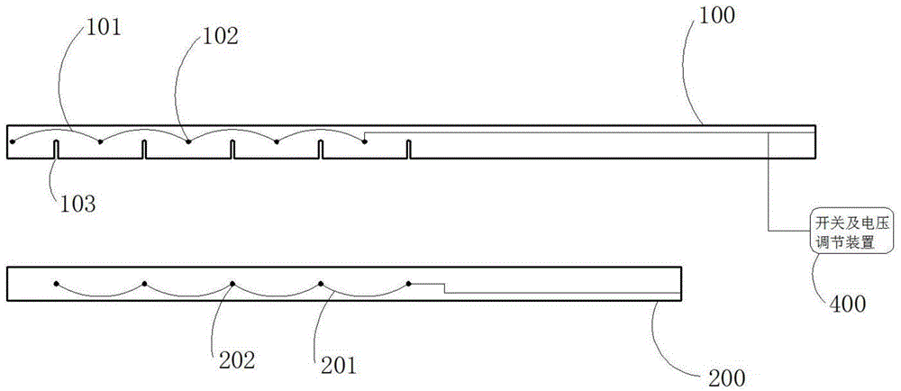
[0034] figure 1 A structural diagram showing an embodiment of the present invention. A plasma comb that treats the scale layer on the surface of human hair and improves the characteristics of the hair scale layer so as to dye and comb the hair. The plasma comb includes a positive electrode comb plate 100, a negative electrode comb plate 200, a positive electrode comb tooth 102, and a negative electrode comb Teeth 202 , wires,...
PUM
 Abstract
Description
Claims
Application Information
 - Generate Ideas
- Intellectual Property
- Life Sciences
- Materials
- Tech Scout
- Unparalleled Data Quality
- Higher Quality Content
- 60% Fewer Hallucinations
Browse by: Latest US Patents, China's latest patents, Technical Efficacy Thesaurus, Application Domain, Technology Topic, Popular Technical Reports.
© 2025 PatSnap. All rights reserved.Legal|Privacy policy|Modern Slavery Act Transparency Statement|Sitemap|About US| Contact US: help@patsnap.com