Supercharge Your Innovation With Domain-Expert AI Agents!

Brake device for remotely controlling axial flow fan

An axial flow fan and remote control technology, which is applied in the direction of braking action starting device, pump control, brake, etc., can solve the problems of low braking reliability and inconvenient operation, and achieve improved reliability, convenient operation and simple maintenance Effect

Inactive Publication Date: 2015-02-18
SHANXI ANRUI FAN ELECTRIC
View PDF8 Cites 0 Cited by
  • Summary
  • Abstract
  • Description
  • Claims
  • Application Information

AI Technical Summary

Problems solved by technology

[0004] The purpose of the present invention is to overcome the problems of inconvenient operation and low braking reliability of the existing braking device of the axial flow fan, and provide a remote control device capable of remote control, high braking reliability, convenient operation and simple maintenance. Controlling the braking device of the axial flow fan

Method used


Image

  • Brake device for remotely controlling axial flow fan
  • Brake device for remotely controlling axial flow fan
  • Brake device for remotely controlling axial flow fan

Examples


Embodiment 1

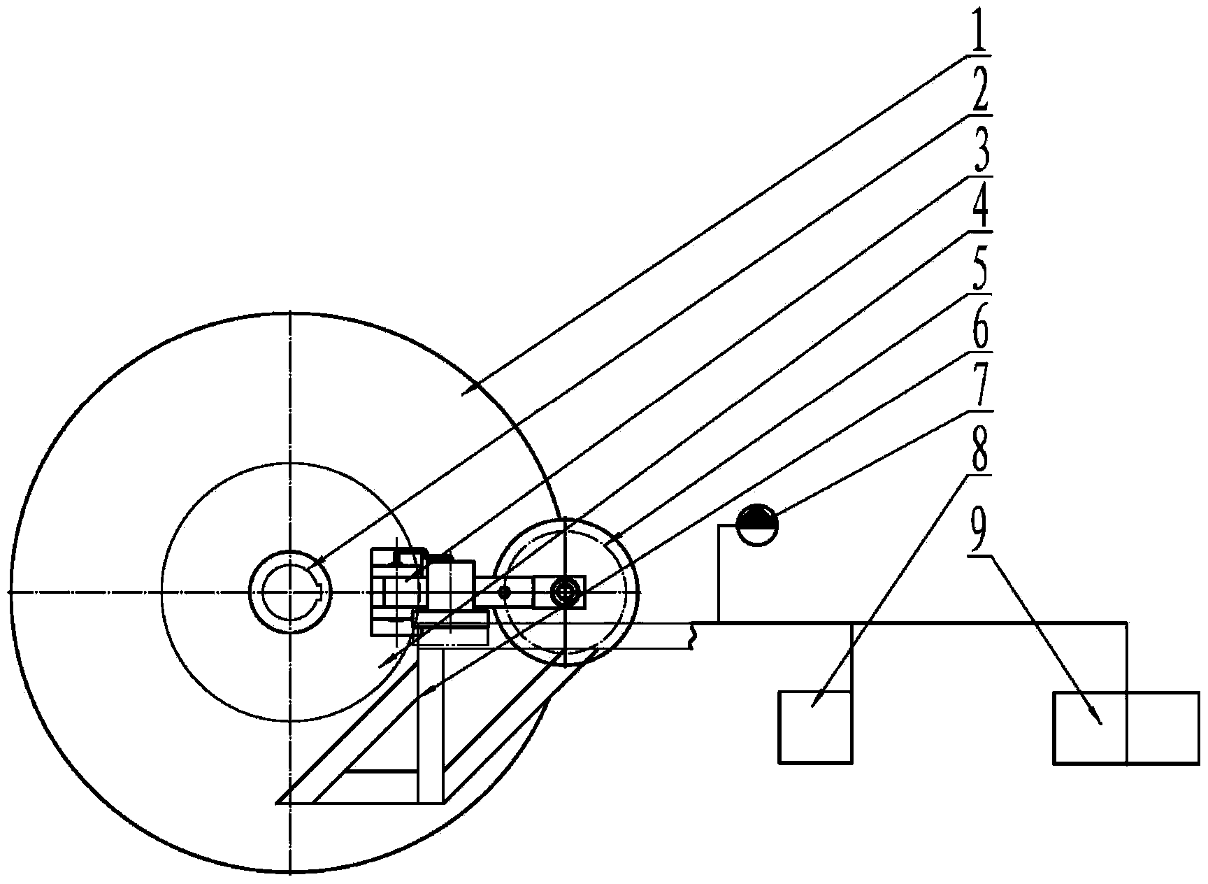
[0020] Braking of a single remote-controlled axial fan brake requires only a set of remote-controlled axial fan brakes. The brake disc of the disc brake system is installed on the rear extension shaft of the motor, and the main body of the electromagnetic brake is fixed on the On the inner wall of the isolation chamber of the mine axial flow fan, the electromagnetic relay with 485 interface and the speed sensor are installed on the main body of the electromagnetic brake. The electromagnetic relay with 485 interface is located outside the brake disc, and the speed sensor is located at the rear of the motor Outer end; the speed sensor detects the speed of the motor in real time, and transmits the detected speed signal to the remote control system through the 485 interface of the electromagnetic relay containing the 485 interface; the local / remote control box is connected to the remote control system, and can Switch between operation and remote operation, and the brake command is ...

Embodiment 2

[0023] According to the needs of the operation, the motors of mine axial flow fans have multiple different models. For motors with high speed and large volume, the required braking torque also increases accordingly. At this time, only one set of remote control axial flow fans is used. The braking device of the fan cannot achieve effective braking. Therefore, it is necessary to install multiple electromagnetic brake bodies and electromagnetic relays with 485 interfaces according to the size of the brake disc.

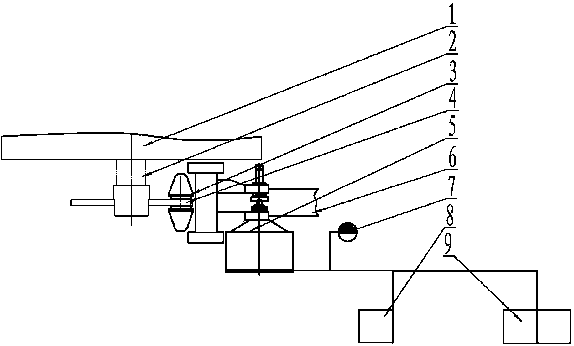
[0024] Such as image 3 As shown, in this embodiment, a brake disc is used to install four electromagnetic brake bodies, four electromagnetic relays with 485 interfaces, and a rotational speed sensor as an example for illustration.

[0025] Four electromagnetic relays with 485 interfaces are respectively installed on four electromagnetic brake main bodies, and the four electromagnetic brake main bodies are all fixed on the inner wall of the flow separation cavity of the ...


PUM


Abstract

The invention discloses a brake device for remotely controlling an axial flow fan. The device comprises a motor, a disc-shaped brake system, an on-site / remote control box and a control system, wherein the disc-shaped brake system comprises a brake disc, an electromagnetic brake main body, an electromagnetic relay containing a 485 interface and a speed sensor; the brake disc of the disc-shaped brake system is mounted on the rear stretching shaft of the motor; when braking is needed, the control system is used for receiving a braking command sent out by the on-site / remote control box and sending a signal to the electromagnetic relay containing the 485 interface, so that the electromagnetic relay is sucked with the brake disc to realize the braking of the motor. According to the brake device, an advanced disc-shaped brake device is designed, remote control is conducted by adopting the control system through the 485 interface, and the brake device has the advantages of high reliability in braking, good convenience in operation, simplicity in maintenance and the like.

Description

technical field [0001] The invention belongs to ventilation equipment, in particular to a brake device for remote control of an axial flow fan. Background technique [0002] The axial flow fan used on the coal mine ground is the main large-scale ventilation equipment in the mine, which directly affects the safe production in the mine. When the ventilator replaces the main engine to start another main engine or directly reverses the return air, it needs to cut off the power for a short time. At this time, it needs to be equipped with a braking device to reduce the spindle speed or brake. [0003] The braking device of the current axial flow fan used in coal mines generally adopts the internal expansion drum brake controlled by a manual pull rod. The control of this braking device can only be performed by using the hand pull rod located at the position of the fan host, and the control operation is very inconvenient. At present, there is no precedent for remote braking of axia...

Claims


Application Information

Patent Timeline
Patent Type & Authority Applications(China)
IPC IPC(8): F04D27/00B60T7/00
Inventor 文军强郭青陇秦满忠杜文渊
Owner SHANXI ANRUI FAN ELECTRIC
Features
  • R&D
  • Intellectual Property
  • Life Sciences
  • Materials
  • Tech Scout
  • Unparalleled Data Quality
  • Higher Quality Content
  • 60% Fewer Hallucinations
Learn More