Heat treatment feeding roller bar

A technology of rollers and sticks, applied in lighting and heating equipment, metal material coating technology, furnace components, etc., can solve the problems of high surface smoothness, low heat treatment efficiency, and affecting feeding speed, etc., to achieve smooth feeding process , reduce surface finish, improve work efficiency

Inactive Publication Date: 2015-02-25
重庆戴卡捷力轮毂制造有限公司
5 Cites 0 Cited by

AI-Extracted Technical Summary

Problems solved by technology

The current feeding rollers are made of heat-resistant steel with a smooth surface. Whether manual feeding or automatic feeding is used, the feeding speed will be ...

Abstract

The invention provides a heat treatment feeding roller bar. The heat treatment feeding roller bar comprises a cylindrical roller face and a friction increasing coating sprayed on the roller face, the cylindrical roller face is square hatching knurling and comprises double-walking-direction grooves and square protruding blocks, 45-degree included angles are formed between the walking directions of the grooves and the axial direction of the roller bar, included angles formed between the grooves in different directions are 90 degrees, one diagonal line of each square protruding block is parallel to the axial direction of the roller bar, the other diagonal line of each square protruding block is perpendicular to the axial direction of the roller bar, paint used in the friction increasing coating are WC-TiC-Co cemented carbide powder, and the spraying method is heat spraying. According to the heat treatment feeding roller bar, the shortcoming that in the prior art, the feeding speed is low due to slipping caused by small friction force is overcome by increasing the surface friction force of the roller bar, and the feeding efficiency is improved.

Application Domain

Molten spray coatingCharge manipulation

Technology Topic

Cemented carbideSpray method +6

Image

  • Heat treatment feeding roller bar
  • Heat treatment feeding roller bar
  • Heat treatment feeding roller bar

Examples

  • Experimental program(1)

Example Embodiment

[0019] The following describes the implementation of the present invention through specific specific examples. Those skilled in the art can easily understand other advantages and effects of the present invention from the content disclosed in this specification. The present invention can also be implemented or applied through other different specific embodiments, and various details in this specification can also be modified or changed based on different viewpoints and applications without departing from the spirit of the present invention.
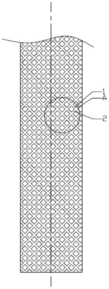
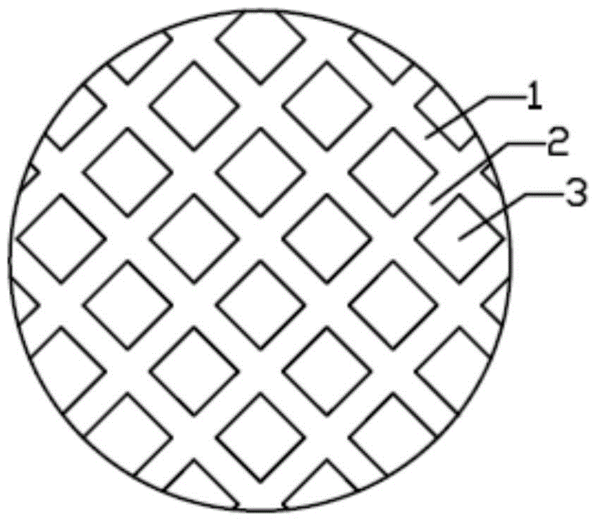
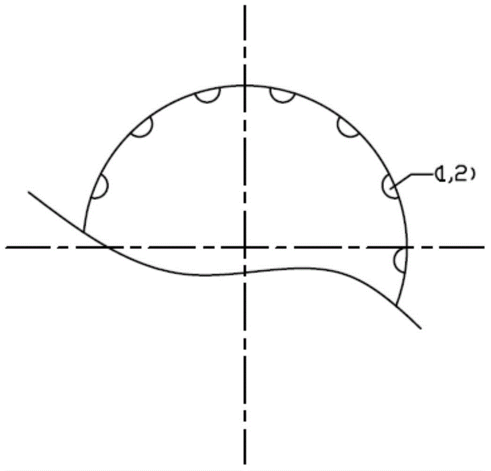
[0020] According to the attached figure 1 The heat-treated feeding rod shown includes a cylindrical roller surface and a friction-increasing coating sprayed on the roller surface. The cylindrical roller surface is square anilox knurled, including double-oriented grooves 1, 2, and square convex Block 3, the groove direction and the roller axis are at an angle of 45°, the angle between the grooves in different directions is 90°, one diagonal of the square bump 3 is parallel to the roller axis, and the other is diagonal The line is perpendicular to the axis of the roller, see attachment for details figure 2. The spray paint used in the friction-increasing coating is WC-TiC-Co cemented carbide powder, and the spraying method is thermal spraying. The grooves of the heat-treated feeding rods are evenly arranged around the circumference, and the spacing is twice the depth of the grooves.
[0021] According to the attached image 3 As shown, the shape of the groove on the heat-treated feeding rod is semicircular and the depth is 5mm. Prevent materials from remaining in the groove and avoid waste.
[0022] In addition, the grain size of the WC-TiC-Co cemented carbide powder on the surface of the heat-treated feeding rod is 300 mesh.
[0023] In addition, the thickness of the grinding layer on the surface of the heat-treated feeding rod is 200 μm.

PUM

no PUM

Description & Claims & Application Information

We can also present the details of the Description, Claims and Application information to help users get a comprehensive understanding of the technical details of the patent, such as background art, summary of invention, brief description of drawings, description of embodiments, and other original content. On the other hand, users can also determine the specific scope of protection of the technology through the list of claims; as well as understand the changes in the life cycle of the technology with the presentation of the patent timeline. Login to view more.

Similar technology patents

Pulling cord winder for venetian blind

InactiveUS20060175022A1increase friction
Owner:CHENG LI MING

Anti-skid device for automobile

InactiveCN103552427Aincrease frictionGood anti-skid effect
Owner:张治国

Looper

InactiveCN105603642AImprove cloth feeding efficiencyincrease friction
Owner:孝感华越机电科技有限公司

Tractor for magnetic levitation traffic installation routing inspection rescue

InactiveCN104139787Aincrease friction areaincrease friction
Owner:成都金和工贸有限公司

Classification and recommendation of technical efficacy words

  • increase friction

Medical closure device

InactiveUS20090234377A1increase friction
Owner:ST JUDE MEDICAL SYST

Expansion dowel

InactiveUS20080050195A1increase frictionwell control
Owner:HILTI AG

Electronic cicarette

InactiveUS20160262449A1increase frictionprevent their use
Owner:KIMREE HI TECH
Why Eureka
Try Eureka