Check patentability & draft patents in minutes with Patsnap Eureka AI!

Synthetic aperture ultrasonic imaging motion compensation method

A synthetic aperture and ultrasonic imaging technology, applied in the field of motion compensation, can solve problems such as ineffective motion compensation, and achieve the effect of improving imaging quality

Inactive Publication Date: 2015-03-25
INST OF ACOUSTICS CHINESE ACAD OF SCI
View PDF3 Cites 3 Cited by
  • Summary
  • Abstract
  • Description
  • Claims
  • Application Information

AI Technical Summary

Problems solved by technology

[0004] The purpose of the present invention is to overcome the defect that the prior art cannot perform effective motion compensation for the situation that the axial displacements at different lateral positions of the imaging plane are different, thereby providing effective motion compensation for the situation where the axial movement rate of the imaging plane is uniform Synthetic Aperture Ultrasound Imaging Motion Compensation Method

Method used


Image

  • Synthetic aperture ultrasonic imaging motion compensation method
  • Synthetic aperture ultrasonic imaging motion compensation method
  • Synthetic aperture ultrasonic imaging motion compensation method

Examples


Embodiment Construction

[0041] The present invention will be further described now in conjunction with accompanying drawing.

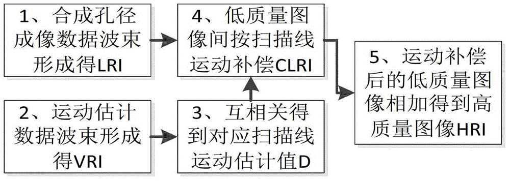
[0042] The synthetic aperture ultrasonic imaging motion compensation method of the present invention aims at different axial displacements at different lateral positions of the imaging plane, and performs motion compensation on each scanning line in a low-quality image, thereby realizing high-quality synthetic aperture imaging.

[0043] Generally speaking, the motion compensation method for synthetic aperture ultrasonic imaging of the present invention includes two stages: one is the signal acquisition stage, and the other is the signal processing stage.

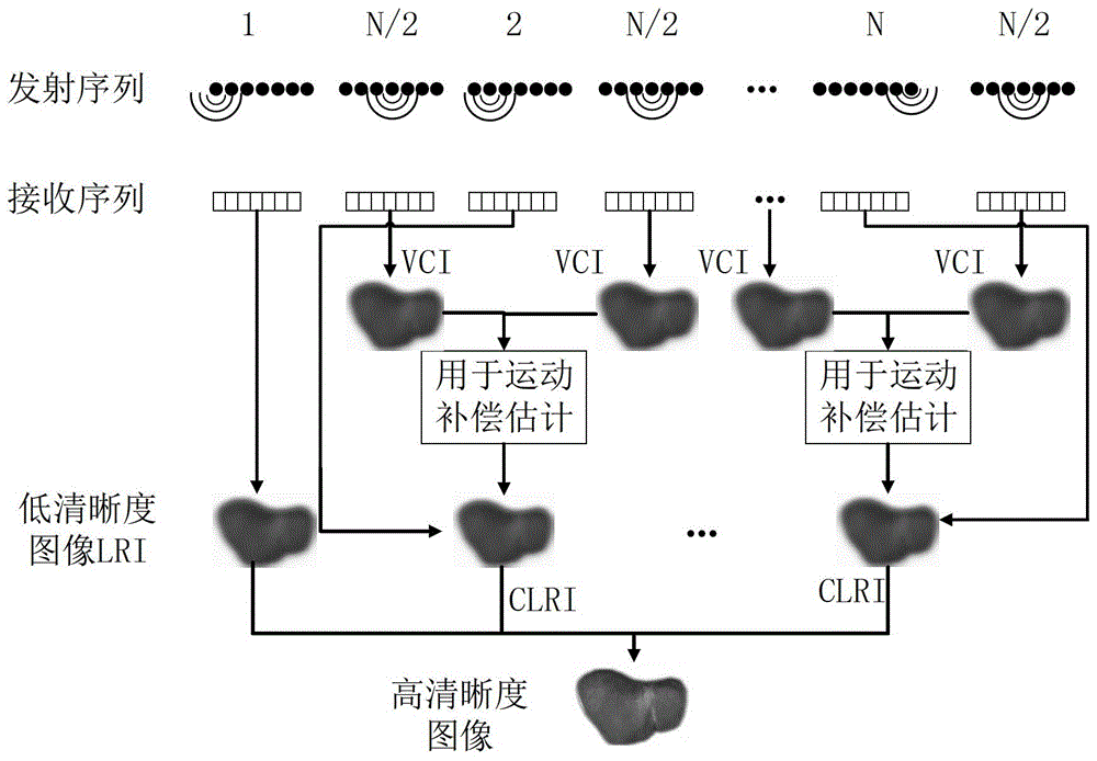
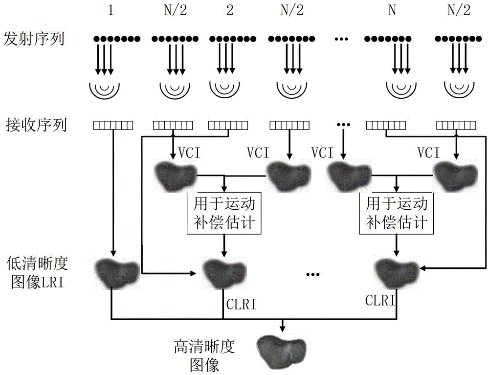
[0044] The signal acquisition includes synthetic aperture imaging data acquisition and motion estimation data acquisition. The implementation of the synthetic aperture imaging data acquisition is: using a single array element in the array or a sub-aperture composed of multiple adjacent array elements to sequentially emit un...


PUM


Abstract

The invention relates to a synthetic aperture ultrasonic imaging motion compensation method which is applied to an array including N array elements. The method includes the steps of obtaining synthetic aperture imaging data, conducting beam forming on the synthetic aperture imaging data to obtain a low-quality image LRI, obtaining motion estimation data, and conducting beam forming on the motion estimation data to obtain a low-quality image VCI; repeatedly executing the synthetic aperture data obtaining operation, and repeatedly executing the motion estimation data obtaining operation, wherein one-time motion estimation data obtaining operation exists between every two times of synthetic aperture imaging data obtaining operation; conducting motion displacement estimation on a series of VCI to obtain the motion estimation value D of each scanning line between the LRI; conducting compensation on each scanning line of the LRI through the motion estimation values D to obtain compensated low-quality images CLRI; adding the first low-quality image LRI and all the CLRI so as to obtain a high-quality image HRI.

Description

technical field [0001] The present invention relates to a motion compensation method, in particular, to a motion compensation method for synthetic aperture ultrasound imaging. Background technique [0002] In synthetic aperture focusing imaging, through the non-focused sound source emission, all the array elements receive the received data point-by-point beamforming to achieve one emission to obtain a low-quality image (LRI), and then through multiple low-resolution The high-quality image (HRI) is obtained by coherent addition of the quality image, so that the transmission and reception point-by-point focusing can be realized without tissue movement, and the resolution of the image can be improved. But the tissue motion between low-quality images will reduce the coherence between low-quality images, thus affecting the imaging quality. There are two ways to solve this problem, one is to increase the frame rate of the system, so that the motion displacement between two low-qu...

Claims


Application Information

Patent Timeline
Patent Type & Authority Applications(China)
IPC IPC(8): G01S7/52G01S15/89
CPCG01S15/89
Inventor 理华孟晓辉肖灵
Owner INST OF ACOUSTICS CHINESE ACAD OF SCI
Features
  • R&D
  • Intellectual Property
  • Life Sciences
  • Materials
  • Tech Scout
  • Unparalleled Data Quality
  • Higher Quality Content
  • 60% Fewer Hallucinations
Learn More