Check patentability & draft patents in minutes with Patsnap Eureka AI!

Post-irradiated fuel rod vacuum bubble method leak detection box, leak detection system and leak detection method

A technology of vacuum bubbles and fuel rods, which is applied in the fields of reducing greenhouse gases, climate sustainability, and monitoring of nuclear reactors. It can solve the problems of high sealing requirements, low detection sensitivity, and difficulty in wide application, and achieves easy installation and structural strength. Guarantee and realize the sealing effect

Active Publication Date: 2017-03-08
NUCLEAR POWER INSTITUTE OF CHINA
View PDF9 Cites 0 Cited by
  • Summary
  • Abstract
  • Description
  • Claims
  • Application Information

AI Technical Summary

Problems solved by technology

The water boiling method changes the pressure difference between the inside and outside of the fuel rod by heating water. Due to the limitation of the boiling point of water, the pressure difference generally produced is about 0.2 atm, and the detection sensitivity is relatively low, so it is rarely used.
The supercharging method uses the supercharging device to press the reference gas into the fuel rod through the damaged port or a special hole to change the pressure difference between the inside and outside of the fuel rod. However, this method requires high sealing performance, is difficult to install, and is difficult to be widely used.

Method used


Image

  • Post-irradiated fuel rod vacuum bubble method leak detection box, leak detection system and leak detection method
  • Post-irradiated fuel rod vacuum bubble method leak detection box, leak detection system and leak detection method
  • Post-irradiated fuel rod vacuum bubble method leak detection box, leak detection system and leak detection method

Examples


Embodiment 1

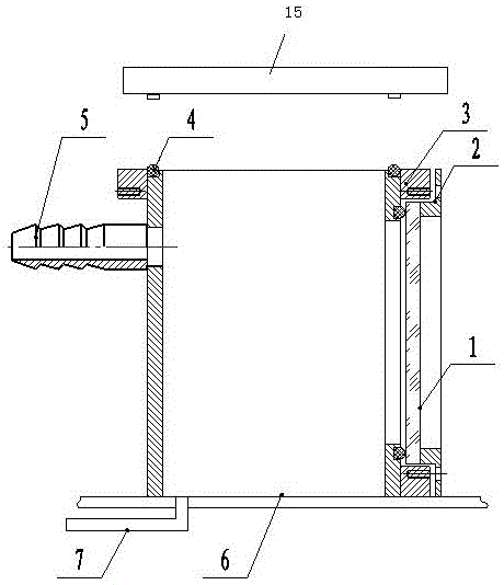
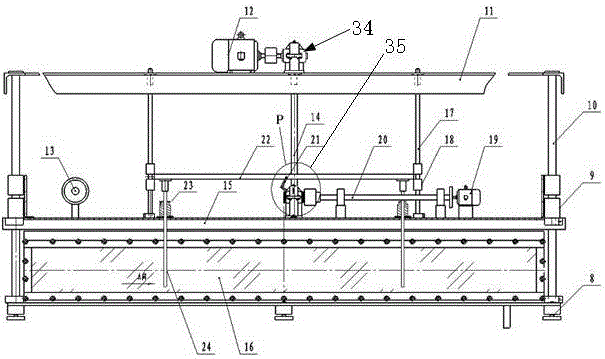
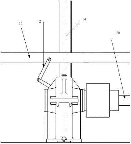
[0062] Such as Figure 1 to Figure 4 shown.

[0063] After irradiation, the fuel rod vacuum bubble method leak detection box includes a leak detection box body 16 with an upper end opening, and a groove is arranged on the upper opening end surface of the leak detection box body, and a sealing strip 4 is arranged in the groove. A cover plate 15 is also arranged above the box body, and the cover plate 15 is provided with a protruding block facing the leak detection box body, and the protruding block is inserted into the groove to seal the upper open end of the leak detection box body.

[0064] Because what the present invention adopts is to carry out leak detection treatment to the fuel rod after irradiation, therefore, the cooperating installation of above-mentioned groove and the protruding block of cover plate 15 realizes automatic positioning through cover plate guide bar 10 and supporting linear bearing slide block 9, At the same time, a protruding block is set under the c...

Embodiment 2

[0077] Based on the leak detection method of the fuel rod vacuum bubble method leak detection system after irradiation, the leak detection method includes the following steps:

[0078] Step A: fuel rod baking step: use a baking device to bake the surface of the fuel rod; because the inspected fuel rod may be damaged, the fuel rod is under the water surface for a long time, and the inside of the fuel rod will enter the liquid due to the pressure. The vacuum bubble method leak detection adopted in the present invention needs to form a hollow inside the damaged fuel rod with a certain amount of gas, and the bubbles at the damaged part can only be observed when the vacuum bubble method is used for leak detection. Therefore, the present invention uses a roasting device to roast the fuel rods to discharge the liquid that may exist inside the fuel rods, while other methods of discharging liquids are not suitable for the target fuel of the present invention due to the narrow environmen...


PUM


Abstract

The invention discloses a fuel rod vacuum bubble method leak detection box after irradiation, a leak detection system and a leak detection method thereof. After irradiation, the fuel rod is dried by a baking device, placed on an L-shaped lifting frame, and then lowered into the leak detection box In the water, a vacuum is drawn inside the leak detection box to generate a pressure difference inside and outside the fuel rod. If the fuel rod is damaged, bubbles will be formed around the damaged opening. The position of the bubble generation is determined by image acquisition, thereby completing the inspection of the irradiated fuel rod. leak detection. This set of device leak detection has the advantages of fast detection speed, simple operation in the hot chamber, good economy, etc., simple structure, low cost, remote manipulator operation, safe structure, no excessive structure contacting fuel rods, making the breach as possible Appears to increase the leak detection rate of fuel rods.

Description

technical field [0001] The patent of the present invention relates to a fuel rod leak detection treatment structure and treatment method. Background technique [0002] At present, the leak detection of fuel rods after irradiation mainly adopts three methods: vacuum bubble method, water boiling method and pressurized method. The water boiling method changes the internal and external pressure difference of the fuel rod by heating water. Due to the limitation of the boiling point of water, the generally generated pressure difference is about 0.2 atm, and the detection sensitivity is relatively low, so it is rarely used. The pressurization method presses the reference gas into the fuel rod through the damaged port or special hole through the pressurization device to change the pressure difference between the inside and outside of the fuel rod. However, this method requires high sealing performance, is difficult to install, and is difficult to be widely used. For a large number ...

Claims


Application Information

Patent Timeline
Patent Type & Authority Patents(China)
IPC IPC(8): G21C17/07
CPCG21C17/07Y02E30/30
Inventor 杨晓冰江林志张显鹏江艳蒋国富宋小蓉李福荣陈军黄伟杰
Owner NUCLEAR POWER INSTITUTE OF CHINA
Features
  • R&D
  • Intellectual Property
  • Life Sciences
  • Materials
  • Tech Scout
  • Unparalleled Data Quality
  • Higher Quality Content
  • 60% Fewer Hallucinations
Learn More