
Fiber fault monitoring method, equipment and system

A fiber optic fault and fiber optic technology, applied in the field of communication, can solve problems such as high equipment cost and long test time

Active Publication Date: 2015-04-15
HUAWEI TECH CO LTD
View PDF4 Cites 11 Cited by
  • Summary
  • Abstract
  • Description
  • Claims
  • Application Information

AI Technical Summary

Problems solved by technology

Therefore, the optical power monitoring equipment is separated from the fault location test equipment, and the fault location test equipment needs to use OTDR to cooperate with optical switches, the equipment cost is high, and the test time is long

Method used


Image

  • Fiber fault monitoring method, equipment and system
  • Fiber fault monitoring method, equipment and system
  • Fiber fault monitoring method, equipment and system

Examples


Embodiment Construction

[0052]The following will clearly and completely describe the technical solutions in the embodiments of the present invention with reference to the accompanying drawings in the embodiments of the present invention. Obviously, the described embodiments are only some, not all, embodiments of the present invention. Based on the embodiments of the present invention, all other embodiments obtained by persons of ordinary skill in the art without creative efforts fall within the protection scope of the present invention.

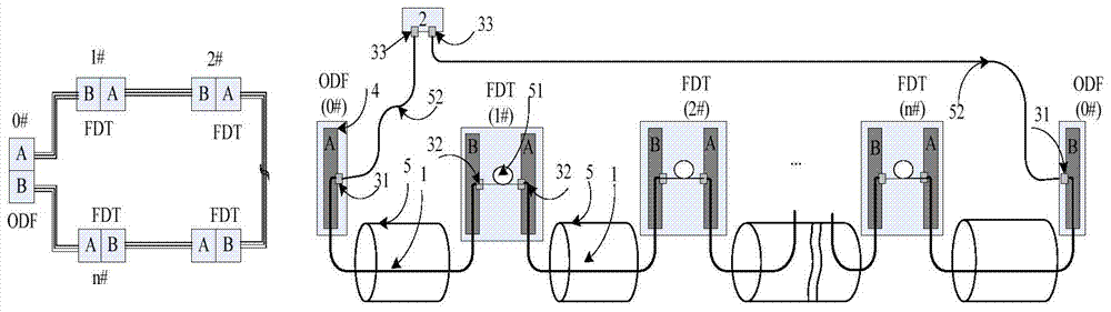
[0053] refer to figure 1 , figure 1 It is an application scenario diagram for monitoring optical cable faults provided by an embodiment of the present invention. Such as figure 1 As shown, the left figure is a ring-shaped optical fiber cable network topology, and the right figure is a schematic diagram of the connection between the test fiber 1 and the node equipment, wherein the optical cable monitoring device 2 and the node equipment backbone optical distributio...


PUM


Abstract

An embodiment of the invention provides a fiber fault monitoring method, equipment and system. The fiber fault monitoring method includes transmitting first test signals from an end A to an end B of an optical fiber to be detected and second test signals from the end B to the end A of the optical fiber to be detected, wherein the end A of the optical fiber to be detected is arranged on a port of an optical fiber distribution frame, and the end B of the optical fiber to be detected is serially connected with the other port of the optical fiber distribution frame through a jump fiber; receiving the first test signals fed back from the end A to the end B of the optical fiber to be detected and the second test signals fed back from the end B to the end A of the optical fiber to be detected respectively; when the optical fiber to be detected has faults, locating the fault points of the optical fiber to be detected according to the feedback first test signals and the feedback second test signals. Accordingly, the purpose to integrate light power monitoring and fault location testing is achieved and cost for monitoring fiber faults is reduced.

Description

technical field [0001] The present invention relates to the communication field, in particular to a method, equipment and system for monitoring optical fiber faults. Background technique [0002] The optical cable monitoring system can judge whether the optical cable is running normally by monitoring the optical cable. When abnormal conditions occur, an alarm will be issued and corresponding tests will be carried out to accurately locate the point of failure. [0003] The optical cable monitoring system uses the alarm indication unit (Alarm Indication Unit, AIU) to monitor the power in the optical fiber, so as to monitor the attenuation change of the optical fiber. When the fiber attenuation is greater than a certain threshold, or the received optical power monitoring is less than a certain value, an optical cable fault alarm is generated. When an alarm occurs, the operator controls the Optical Switching Unit (OSU) to connect the OTDR to the backup fiber port to test the s...

Claims


Application Information

Patent Timeline
IPC IPC(8): H04B10/071
Inventor 赵峻
Owner HUAWEI TECH CO LTD
Features
  • Generate Ideas
  • Intellectual Property
  • Life Sciences
  • Materials
  • Tech Scout
  • Unparalleled Data Quality
  • Higher Quality Content
  • 60% Fewer Hallucinations
Learn More