Check patentability & draft patents in minutes with Patsnap Eureka AI!

Optical Imaging Lens

An optical imaging lens and imaging technology, applied in the direction of optics, optical components, lenses, etc., can solve the problems of peripheral damage and lower production yield, and achieve the effect of improving yield and increasing thickness

Active Publication Date: 2017-05-10
GENIUS ELECTRONICS OPTICAL XIAMEN
View PDF5 Cites 0 Cited by
  • Summary
  • Abstract
  • Description
  • Claims
  • Application Information

AI Technical Summary

Problems solved by technology

The difficulty often encountered in reality is that the peripheral parts 121B, 122B, 123B, and 124B are often damaged during the demoulding process, thus reducing the production yield
[0004] Therefore, how to meet consumers' needs for thin and light appearance and image quality, and at the same time overcome the problem of lens damage during the production process is a major challenge that needs to be solved urgently.

Method used


Image

  • Optical Imaging Lens
  • Optical Imaging Lens
  • Optical Imaging Lens

Examples


Embodiment Construction

[0045] To further illustrate the various embodiments, the present invention is provided with accompanying drawings. These drawings are a part of the disclosure of the present invention, which are mainly used to illustrate the embodiments, and can be combined with the relevant descriptions in the specification to explain the operating principles of the embodiments. With reference to these contents, those skilled in the art should understand other possible implementations and advantages of the present invention. Components in the figures are not drawn to scale, and similar component symbols are generally used to denote similar components.

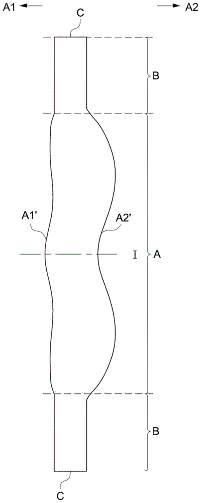
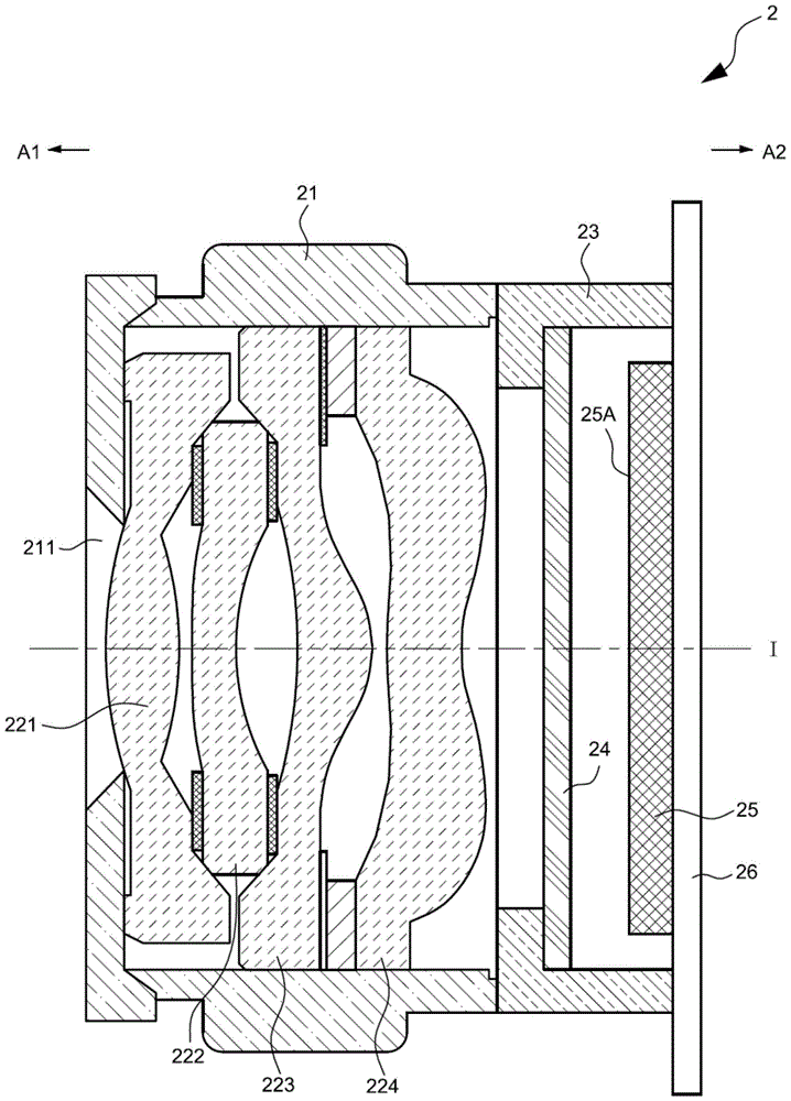
[0046] The lens structure proposed by the present invention is as figure 2As shown, each lens is formed with a lens portion A, and a peripheral portion B is formed between the outside of the lens portion A and the outer edge C of the lens. The lens portion A forms an object side A1' for passing imaging light toward the object side A1, and ...


PUM


Abstract

The invention provides an optical imaging lens. The optical imaging lens comprises: a lens barrel; In the direction of the object side, an object side is formed to allow the imaging light to pass through, and an image side is formed in the direction toward the image side to allow the imaging light to pass through. There is an embedded lens in the lens, and the lens center of the embedded lens extends to the outside of the lens. The radius of the edge is smaller than the radius from the center of the adjacent lens to the outer edge of the lens, and the outer edge of the embedded lens is embedded in the outer periphery of the adjacent lens. The invention is applied in lens manufacturing and assembly of optical lenses.

Description

technical field [0001] The present invention relates to an optical imaging lens, and in particular to an optical imaging lens of an electronic device. Background technique [0002] In recent years, the popularization of mobile phones and digital cameras has made the related industries of optical imaging lenses develop vigorously. , referred to as CCD) or complementary metal oxide semiconductor components (Complementary Metal-Oxide Semiconductor, referred to as CMOS) technological progress and size reduction, the lens mounted in the optical imaging lens also needs to reduce the thickness, but the good optical performance of the optical imaging lens is also necessary considerations. [0003] Please refer to figure 1 The structure of the conventional lenses 121 , 122 , 123 , 124 loaded in the conventional optical imaging lens 1 is shown. In response to the above-mentioned requirement of reducing the thickness, the appearance of the conventional lenses 121, 122, 123, 124 is l...

Claims


Application Information

Patent Timeline
Patent Type & Authority Patents(China)
IPC IPC(8): G02B7/02G02B7/00G03B30/00
CPCG02B7/00G02B7/021G02B13/004G02B3/00G02B13/0035
Inventor 侯锨锠
Owner GENIUS ELECTRONICS OPTICAL XIAMEN
Features
  • R&D
  • Intellectual Property
  • Life Sciences
  • Materials
  • Tech Scout
  • Unparalleled Data Quality
  • Higher Quality Content
  • 60% Fewer Hallucinations
Learn More