Novel transformer core positioning structure and method

A positioning structure and positioning method technology, applied in the direction of inductor/transformer/magnet manufacturing, transformer/inductor magnetic core, transformer/inductor parts, etc. To solve problems such as large thickness, achieve the effect of improving the no-load current value and noise level value, alleviating the increase of magnetic density, and reducing the diffraction size

Active Publication Date: 2015-04-29
南京大全变压器有限公司
View PDF5 Cites 4 Cited by
  • Summary
  • Abstract
  • Description
  • Claims
  • Application Information

AI Technical Summary

Problems solved by technology

At present, the market competition at home and abroad is becoming increasingly fierce, and the cost of human resources is also getting higher and higher. How to improve labor productivity is one of the main directions of transformer manufacturing enterprises. In my country's transformer manufacturing enterprises, the lamination of iron cores is mainly done by manpower. Completed, and the thickness of the laminations of the mainstream oblong core structure is large, and the number of man-hours for manual laminations is large, which not only affects the production schedule, but also increases labor costs
In order to improve the efficiency of core lamination, process holes are often added to the core, such as figure 1 As shown, this can reduce the time for trimming the iron core, but the effect

Method used


Image

  • Novel transformer core positioning structure and method
  • Novel transformer core positioning structure and method
  • Novel transformer core positioning structure and method

Examples


Example Embodiment

[0023] In order for the examiner to better understand the technical features, technical content and technical effects achieved by the present invention, the drawings of the present invention will now be described in more detail in conjunction with the embodiments. However, the drawings shown are only to better illustrate the technical solution of the present invention, and are not the true proportions and optimal configuration of the present invention. Therefore, the examiner is requested not to limit the scope and configuration of the present invention based on the comparison and configuration of the drawings. Claim protection scope.

[0024] The patent of the present invention will be further described below in conjunction with the drawings and embodiments.

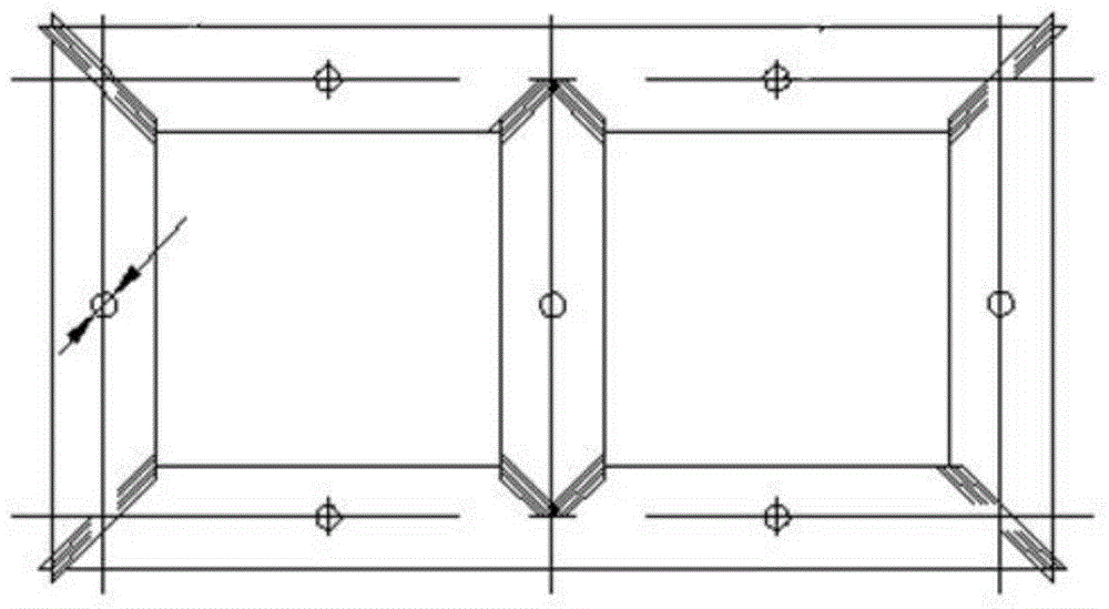
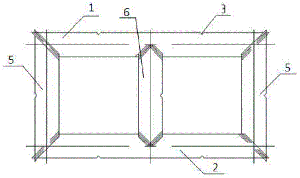
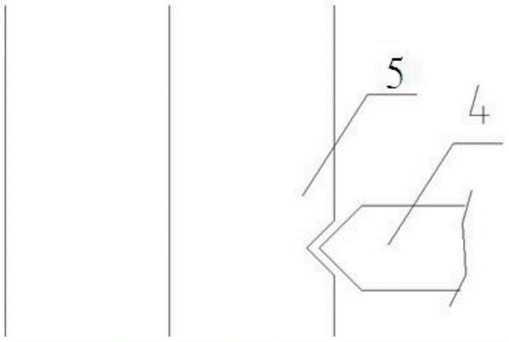
[0025] Such as Figure 1-3 As shown, the present invention provides a novel positioning structure for a transformer core, which includes an iron core and a tooling profile 4, the upper end of the iron core is provided with ...


PUM

PropertyMeasurementUnit
Heightaaaaaaaaaa
Heightaaaaaaaaaa

Abstract

The invention provides a novel transformer core positioning structure and method. The novel transformer core positioning structure comprises a core and a tooling explorator. The upper end of the core is provided with an upper yoke, and the lower end of the core is provided with a lower yoke. Side columns are arranged on two lateral sides of the core. A middle column is arranged in the middle of the core and parallel to the side columns. The side columns are perpendicular to the yokes. The yokes, the side columns and the middle column are provided with positioning holes in rectangular shapes. The end of the tooling explorator is rectangular shaped and matched with the rectangular positioning holes. According to the arrangement, the traditional core positioning holes are modified, the circular core center holes are transformed into rectangular positioning holes in the edges of a silicon steel sheet, allowing section area of core punched hole to be decreased by 80%, then diffraction size of main flux of the core punched hole is reduced, and increasing of local flux density at the core holes is curbed, so that core loss, no-load current value and noise level value are improved.

Description

technical field [0001] The invention relates to the technical field of transformer core structures, in particular to a novel positioning structure and positioning method for transformer cores. Background technique [0002] With the continuous development of transformer industry technology, the performance level of transformers is getting higher and higher, and high efficiency and energy saving are the main trends in the development of transformers. At present, the market competition at home and abroad is becoming increasingly fierce, and the cost of human resources is also getting higher and higher. How to improve labor productivity is one of the main directions of transformer manufacturing enterprises. In my country's transformer manufacturing enterprises, the lamination of iron cores is mainly done by manpower. In addition, the mainstream oblong iron core structure has a large lamination thickness, which requires many man-hours for manual lamination, which not only affects ...

Claims


Application Information

Patent Timeline
IPC IPC(8): H01F27/26H01F27/245H01F41/02
Inventor 蒋忠金郑建银
Owner 南京大全变压器有限公司
Why Eureka
Try Eureka