Check patentability & draft patents in minutes with Patsnap Eureka AI!

Coil-adjustable wireless charger base

A wireless charger, adjustable technology, applied in the direction of current collectors, electric vehicles, electrical components, etc., can solve the problems of unfavorable users for mobile devices, inability to move mobile devices casually, poor user experience of wireless chargers, etc., to improve Use experience, improve anti-slip effect, reduce impact effect

Inactive Publication Date: 2015-04-29
FORYOU MULTIMEDIA ELECTRONICS
View PDF4 Cites 2 Cited by
  • Summary
  • Abstract
  • Description
  • Claims
  • Application Information

AI Technical Summary

Problems solved by technology

Tablet wireless charger bases are usually placed flat on a horizontal surface when used, so in order to achieve the charging effect, the mobile device must also be placed on the vertical top surface of the base, and the user cannot move the mobile device casually, which is not conducive to the user's use of the mobile device , resulting in a poor user experience of the wireless charger
In different mobile devices, the installation position of the receiver is also different. Correspondingly, every time it is charged with the base, the position of the mobile device must be adjusted frequently, which is extremely inconvenient to use.

Method used


Image

  • Coil-adjustable wireless charger base
  • Coil-adjustable wireless charger base
  • Coil-adjustable wireless charger base

Examples


Embodiment 1

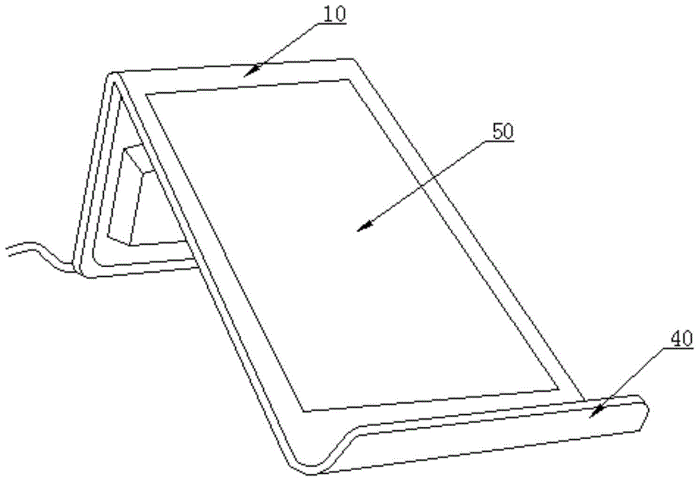
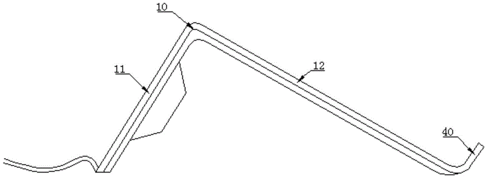
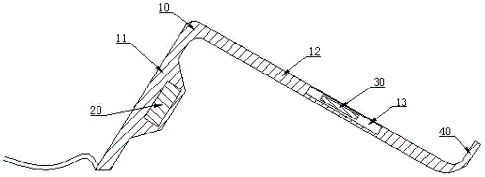
[0022] This embodiment provides a coil-adjustable wireless charger base, which includes a charger bracket 10 on which a power management module 20 and a transmitter coil 30 are arranged. The charger bracket 10 includes a support portion 11 and a charging panel 12 , and the support portion 11 and the charging panel 12 are arranged at an angle. A groove 13 for placing the transmitting end coil 30 is opened in the charging panel 12 , and the transmitting end coil 30 is disposed in the groove 13 . An opening 14 is opened on the bottom surface of the charging panel 12 , and a movable boss 15 is arranged on the opening 14 . The boss 15 is connected to the transmitter coil 30 for adjusting the position of the transmitter coil 30 . The adjustable coil is convenient for matching with mobile devices of different sizes, which increases the compatibility of the embodiments of the present invention.

Embodiment 2

[0024] As a preferred technical solution, the difference between this embodiment and Embodiment 1 is that the angle between the charging panel 12 and the horizontal plane may be, but not limited to, 30°-80°. When the mobile device is placed on the charging panel 12 for charging, the angle between the mobile device and the horizontal plane is 30°-80°, which conforms to the appropriate viewing angle of the human eye, and is convenient for the user to use the mobile device during charging.

Embodiment 3

[0026] As a preferred technical solution, the difference between this embodiment and Embodiment 1 or 2 is that a stopper 40 is also provided at the bottom of the charging panel 12 . The stopper 40 prevents the mobile device from sliding down when placed on the charging panel 12 for charging, improves the accuracy of docking the receiving coil of the mobile device with the present invention, and reduces the power loss caused by docking errors during charging.


PUM


Abstract

The invention relates to the field of design of wireless chargers, in particular to a coil-adjustable wireless charger base, which comprises a charger bracket, wherein a power management module and a transmitter coil are arranged on the charger bracket; the charger bracket comprises a support part and a charging panel; the support part and the charging panel forms an angle; a groove for placing the transmitter coil is formed in the charging panel; an opening is formed in the bottom surface of the charging panel; a movable lug boss is arranged on the opening, and is connected with the transmitter coil, and is used for regulating the position of the transmitter coil. Due to the adoption of the technical scheme, the coil-adjustable wireless charger base can be conveniently used for mobile equipment, and the use experiences of a wireless charger are improved; the adjustable coil can be conveniently matched with mobile equipment with different sizes, so that the compatibility of the coil-adjustable wireless charger base is improved.

Description

technical field [0001] The invention relates to the field of wireless charger design, in particular to a coil-adjustable wireless charger base. Background technique [0002] A wireless charger refers to a device that uses the principle of electromagnetic wave induction for charging, which is similar to a transformer. There is a coil at the sending and receiving ends. The coil at the sending end is connected to a wired power supply to generate an electromagnetic signal, and the coil at the receiving end induces the electromagnetic signal at the sending end to generate current to charge the battery. [0003] It can be known from the principle of the wireless charger that the wireless charger includes a base for emitting electromagnetic waves and a receiver for inducing electromagnetic waves. Most of the existing wireless charging bases in the market are designed in the shape of a tablet, while the receiver is fixedly installed inside or on the back shell of the mobile device....

Claims


Application Information

Patent Timeline
Patent Type & Authority Applications(China)
IPC IPC(8): H02J7/00H02J17/00H02J50/10
CPCH02J7/025
Inventor 吕艳斌
Owner FORYOU MULTIMEDIA ELECTRONICS
Features
  • R&D
  • Intellectual Property
  • Life Sciences
  • Materials
  • Tech Scout
  • Unparalleled Data Quality
  • Higher Quality Content
  • 60% Fewer Hallucinations
Learn More