A buck circuit and a method for maximum power point tracking based on the buck circuit
A technology of maximum power point and circuit, applied in the field of solar energy conversion, can solve the problems of output voltage fluctuation, increase the CPU burden, occupy a lot of CPU time, etc., and achieve the effect of high efficiency, small ripple, and fast tracking speed.
- Summary
- Abstract
- Description
- Claims
- Application Information
AI Technical Summary
Problems solved by technology
Method used
Image

Examples
Embodiment 1
[0101] Example 1: BUCK circuit
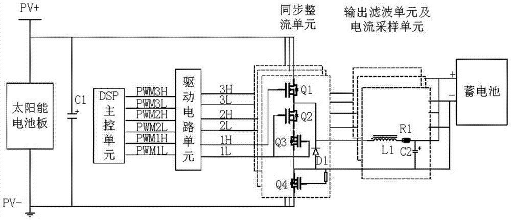
[0102] A BUCK circuit, including a solar panel and a storage battery, is characterized in that: between the solar panel and the storage battery: an input filter unit: composed of a capacitor C1; a main control unit: mainly used to generate control signals; a Synchronous rectification unit: composed of MOS transistor Q1, MOS transistor Q2 and Schottky diode D1; a drive circuit unit: used to drive the synchronous rectification unit and output three PWMs; an output filter unit: composed of inductor L1 and capacitor C2 , used to store energy; a current sampling unit: composed of a resistor R1, a reverse current protection unit: composed of R1 and DSP, an overcurrent protection unit: composed of R1 and DSP.
[0103] Further, it also includes a MOS tube Q4 for preventing battery reverse connection;
[0104] Further, MOS transistor Q2 and MOS transistor Q3 are also included, and Q2 and Q3 are connected in parallel as the lower bridge arm of the synch...
Embodiment 2
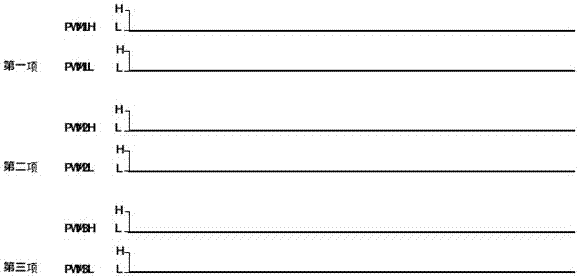
[0105] Example 2: Turn off charging
[0106] like figure 2 As shown, when it is detected that the voltage of the solar panel is lower than the battery voltage (at night), over temperature, etc., the charging needs to be turned off. When it is turned off, the PWMH and PMWL of the three items output low levels.
Embodiment 3
[0107] Example 3: Starting the maximum power point tracking process
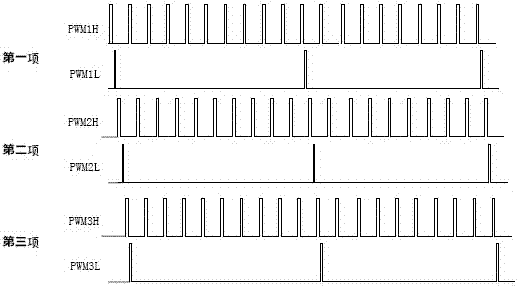
[0108] 1. Start the charging process
[0109] like image 3 As shown, it is detected that the voltage of the solar panel exceeds the voltage of the battery (daytime) and there is no abnormality, and the charging process is started. During this process, the output PWM is output according to the following rules:
[0110] 1) All three items work;
[0111] 2) The three items are 120 degrees wrong with each other;
[0112] 3) The three PWM upper and lower tubes all retain dead zones and PWML lags behind PWMH;
[0113] 4) PWMH keeps the duty cycle minimum and the frequency is 40KHz;
[0114] 5) PWML keeps the duty cycle minimum and the frequency is 4KHz.
[0115] 2. Start maximum power point tracking
[0116] like Figure 4 As shown, after the previous process is completed, the DSP automatically enters the start-up tracking process, and the output PWM is output according to the following rules during this p...
PUM
 Abstract
Description
Claims
Application Information
 - R&D
- Intellectual Property
- Life Sciences
- Materials
- Tech Scout
- Unparalleled Data Quality
- Higher Quality Content
- 60% Fewer Hallucinations
Browse by: Latest US Patents, China's latest patents, Technical Efficacy Thesaurus, Application Domain, Technology Topic, Popular Technical Reports.
© 2025 PatSnap. All rights reserved.Legal|Privacy policy|Modern Slavery Act Transparency Statement|Sitemap|About US| Contact US: help@patsnap.com