Data receiver, data receiving system and data transmission system

A data transmission and receiver technology, applied in the field of data transmission, can solve problems such as inability to transmit, reduce the effective rate of data transmission, increase the complexity of chip or system design, and achieve the effect of improving synchronization

Active Publication Date: 2015-04-29
BRITE SEMICON SHANGHAI CORP
View PDF5 Cites 8 Cited by
  • Summary
  • Abstract
  • Description
  • Claims
  • Application Information

AI Technical Summary

Problems solved by technology

This synchronization method increases the delay of data transmission, increases the complexity of chip or system design, and reduces the effective rate of data transmission to a certain extent.
In addition, the conversion clock of the serial-to-parallel conversio

Method used


Image

  • Data receiver, data receiving system and data transmission system
  • Data receiver, data receiving system and data transmission system
  • Data receiver, data receiving system and data transmission system

Examples


Example Embodiment

[0031] In order to make the above objectives, features and advantages of the present invention more obvious and understandable, the following combination Attached drawing The present invention will be further described in detail with specific embodiments.

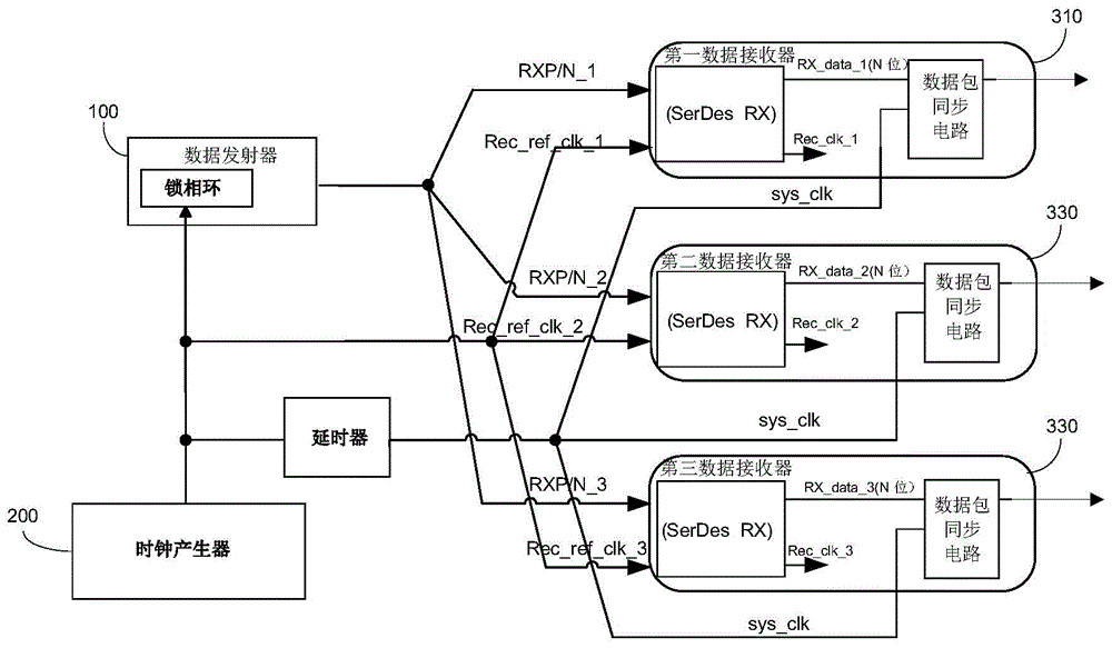
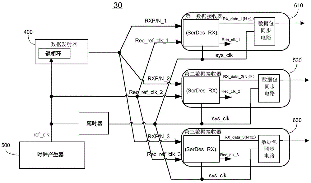
[0032] image 3 It is a schematic diagram of the structure of the data transmission system 30 in an embodiment of the present invention Figure . The data transmission system 30 includes a data transmitter 400, a clock generator 500, a first data receiver 610, a second data receiver 620, and a third data receiver 630. In this example, three data receivers are shown. In fact, there may be two, four or more data receivers. The following uses three data receivers as an example. Each data receiver can be called a data receiving channel, so the data transmission system can also be called a multi-channel data receiving system, and the data received by multiple channels need to be synchronized with each other.

[0033] The clock gene...


PUM


Abstract

The invention provides a data receiver, a data receiving system and a data transmission system. The data receiver comprises a sampling clock generation circuit, a serial data sampling circuit, a clock selection circuit and a series-to-parallel conversion circuit. The sampling clock generation circuit generates multiple sampling clock signals which have the same frequency and a preset phase difference according to recovery reference clock signals. The serial data sampling circuit collects data transmission signals according to the sampling clock signals to obtain a series of serial receiving data. The clock selection circuit selects one proper sampling clock signal from the sampling clock signals to serve as a series-parallel conversion clock signal. The series-parallel conversion circuit converts the serial receiving data from the serial data sampling circuit into parallel receiving data according to the series-parallel conversion clock signal. Due to the fact that the most proper sampling clock signal is selected from the sampling clock signals to serve as the series-parallel conversion clock signal according to the system clock signals, the synchronism among the data received by all data receivers can be improved.

Description

【Technical field】 [0001] The invention relates to the field of data transmission, in particular to a data receiver, a data receiving system and a data transmission system. 【Background technique】 [0002] With the development of electronic industry technology, especially in the development of transmission interface, IEEE1284 is replaced by USB (Universal Serial Bus) interface, PATA (Parallel Advanced Technology Attachment) is replaced by SATA (Serial Advanced Technology Attachment), PCI (Peripheral Component Interconnect ) was replaced by PCI-Express, none of which proved that the speed of the traditional parallel interface has reached a bottleneck, replaced by a faster serial interface, so SerDes (SERDES is a SERializer (serializer) originally used for optical fiber communication Device) / DESerializer (abbreviation for deserializer) technology has become the mainstream for high-speed serial interfaces. The serial interface mainly uses differential signal transmission technol...

Claims


Application Information

Patent Timeline
IPC IPC(8): H04L1/00H04L7/00
CPCH04L7/00H04L69/32
Inventor 周玉镇戴颉李耿民职春星
Owner BRITE SEMICON SHANGHAI CORP
Why Eureka
Try Eureka