Check patentability & draft patents in minutes with Patsnap Eureka AI!

Vehicle safe driving area detection method and device corrected by inertial measurement device

An inertial measurement device and driving area technology, applied in the direction of measurement devices, radio wave measurement systems, electromagnetic wave reradiation, etc., can solve the problems of blurred camera imaging, decreased recognition accuracy, and inability to recognize road slope information, etc., to improve accuracy rate effect

Active Publication Date: 2017-06-20
长春长光精密仪器集团有限公司
View PDF4 Cites 0 Cited by
  • Summary
  • Abstract
  • Description
  • Claims
  • Application Information

AI Technical Summary

Problems solved by technology

Among them, the detection area of ​​the detection method using sensors such as millimeter-wave radar is narrow, and it cannot detect small-sized targets, and it cannot recognize details such as road slope information.
In addition, the detection method using the image sensor shows that the function of the recognition algorithm is not perfect, and the correct recognition rate of the target in the field of view is only 60%-70%. The recognition accuracy rate drops further, and the image quality of the camera is greatly affected by the ambient light, so it cannot work at night
Therefore, the detection effect of the above two methods is very limited.

Method used


Image

  • Vehicle safe driving area detection method and device corrected by inertial measurement device
  • Vehicle safe driving area detection method and device corrected by inertial measurement device
  • Vehicle safe driving area detection method and device corrected by inertial measurement device

Examples


Embodiment 1

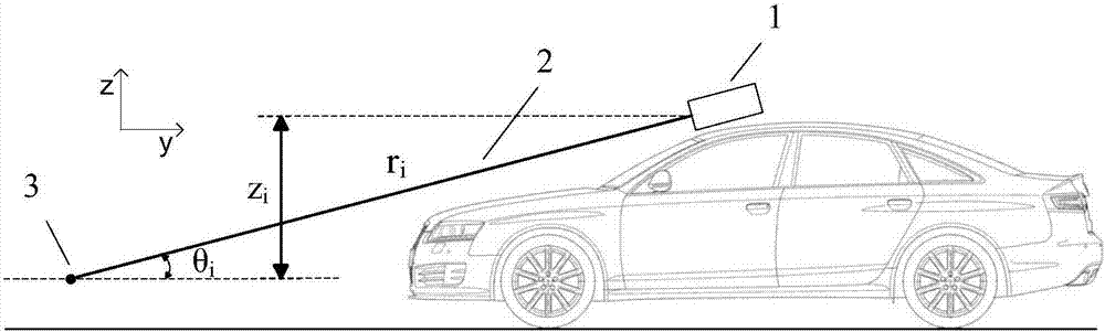
[0020] Such as figure 1 with figure 2 As shown, it is a schematic diagram of the working principle of the laser radar in the embodiment of the present invention, and the laser radar 1 is fixed above the vehicle, but not limited to figure 1 with figure 2 The installation method shown in , can also be installed in other positions of the vehicle, such as the front bumper of the vehicle, and the detection range of this installation method will be reduced. When installing, the laser radar 1 is slightly tilted downward, so that it forms a certain angle on the ground, that is, the elevation angle θ of the laser beam, and scans the road ahead to generate the laser beam 2, which is the sampling point that can obtain continuous ranging in the x-axis direction. 3.

[0021] Set the laser emission point of the laser radar at the starting point of the vehicle's driving within a data collection section unit (for example, the vehicle has traveled a distance of L meters) as the circle poi...

Embodiment 2

[0060] Such as Figure 7 As shown, it is a schematic structural diagram of a vehicle safe driving area detection device corrected by an inertial measurement device according to Embodiment 2 of the present invention, which includes: a data collection module 701 for collecting the coordinates of sampling points output by a laser radar fixed on a vehicle Data; road surface profile data generation module 702, for generating the road surface profile data of spatial Cartesian coordinate form according to coordinate data; Data correction module 703, for collecting and the laser radar that the inertial measurement device linkage of laser radar outputs outputs the angle on the pitch direction Change value, utilize angle change value to correct coordinate data or road surface contour data; Center of gravity coordinate data generation module 704, be used for processing road surface contour data, obtain the center of gravity coordinate data of a plurality of space boxes; Space box mark mod...


PUM


Abstract

The invention provides a detection method and a detection device for a safety driving area of a vehicle corrected by an inertial measuring unit. The method comprises the steps of collecting the coordinate data of sampling points output by a laser radar fixed on the vehicle; generating spatial rectangular coordinate type road surface outline data according to the coordinate data; collecting angular variation values of the laser radar output by the inertial measuring unit linked with the laser radar in a pitching direction, and correcting the coordinate data or the pavement outline data by using the angular vibration values; processing the road surface outline data to obtain the areal coordinate data of a plurality of spatial boxes; calculating gradient values between the spatial boxes according to the gravity coordinate data, and marking the plurality of spatial boxes according to the gradient values; and projecting the marked spatial boxes, and carrying out center line generation on a projection processing result to generate the safety driving area of the vehicle. According to the detection method and the detection box provided by the invention, in comparison with the prior art, the safety driving area of the vehicle can be detected, and the detection accuracy of the road surface can be improved.

Description

technical field [0001] The invention relates to road surface detection technology, in particular to a method and device for detecting a safe driving area of ​​a vehicle corrected by an inertial measurement device. Background technique [0002] With the continuous improvement of people's safety requirements in the process of driving, it is hoped that the vehicle can actively detect obstacles on the road and identify which areas of the road are safe to drive. This information is very critical for self-driving vehicles. At the same time For manually driven vehicles, it can also play a role in enriching the active and safe driving of vehicles. [0003] In the prior art, sensors such as millimeter-wave radar or image sensors are mainly used to detect the road surface in front of the vehicle. Among them, the detection method using sensors such as millimeter-wave radar has a narrow detection area, and cannot detect small-sized targets, and cannot recognize details such as road slo...

Claims


Application Information

Patent Timeline
Patent Type & Authority Patents(China)
IPC IPC(8): G01S17/88
CPCG01S17/931
Inventor 王世峰冷雪刘仲禹
Owner 长春长光精密仪器集团有限公司
Features
  • R&D
  • Intellectual Property
  • Life Sciences
  • Materials
  • Tech Scout
  • Unparalleled Data Quality
  • Higher Quality Content
  • 60% Fewer Hallucinations
Learn More