Supercharge Your Innovation With Domain-Expert AI Agents!

Matrix converter and method for compensating for output voltage error

A matrix converter and error compensation technology, which is applied in the field of matrix converter and output voltage error compensation to achieve high-precision control

Inactive Publication Date: 2015-05-20
YASKAWA DENKI KK
View PDF7 Cites 1 Cited by
  • Summary
  • Abstract
  • Description
  • Claims
  • Application Information

AI Technical Summary

Problems solved by technology

Through the above-mentioned commutation control, although it is possible to prevent the short circuit between the lines of the AC power supply and the open circuit of the output of the matrix converter, but the output voltage produces an error.

Method used


Image

  • Matrix converter and method for compensating for output voltage error
  • Matrix converter and method for compensating for output voltage error
  • Matrix converter and method for compensating for output voltage error

Examples


Embodiment Construction

[0037] Hereinafter, embodiments of the matrix converter disclosed in the present application will be described in detail with reference to the drawings. In addition, this invention is not limited to embodiment shown below.

[0038] [1. Structure of matrix converter]

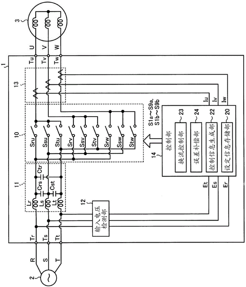
[0039] figure 1 It is a diagram showing a configuration example of a matrix converter according to the embodiment. Such as figure 1 As shown, the matrix converter 1 according to the embodiment is provided between a three-phase AC power source 2 (hereinafter simply referred to as AC power source 2 ) and a load 3 . The load 3 is, for example, an AC motor or a generator. Hereinafter, the R-phase, S-phase, and T-phase of the AC power supply 2 are referred to as input phases, and the U-phase, V-phase, and W-phase of the load 3 are referred to as output phases.

[0040] Matrix converter 1 has: input terminals Tr, Ts, Tt; output terminals Tu, Tv, Tw; power conversion unit 10; LC filter 11; input voltage detection u...


PUM


Abstract

A matrix converter (1) includes a power converter (10), a control information generator (22), a commutation controller (23), a storage (20), and an error compensator (24). The power converter (10) includes bidirectional switches (Sru,Ssu,Stu,Srv,Ssv,Stv,Srw,Ssw,Stw,Sw) each having a conducting direction controllable by switching elements (Swa,Swb). The bidirectional switches (Sru,Ssu,Stu,Srv,Ssv,Stv,Srw,Ssw,Stw,Sw) are disposed between input terminals (Tr,Ts,Tt) and output terminals (Tu,Tv,Tw). The input terminals (Tr,Ts,Tt) are respectively coupled to phases of an AC power source (2). The output terminals (Tu,Tv,Tw) are respectively coupled to phases of a load (3). The control information generator (22) generates control information to control the bidirectional switches (Sru,Ssu,Stu,Srv,Ssv,Stv,Srw,Ssw,Stw,Sw). The commutation controller (23) controls each of the switching elements (Swa,Swb) based on the control information so as to perform commutation control. The storage (20) stores setting information of at least one of a method of the commutation control and a modulation method of power conversion. The error compensator (24) compensates for an output voltage error based on the setting information.

Description

technical field [0001] The invention relates to a matrix converter and a compensation method for output voltage errors. Background technique [0002] The matrix converter has a plurality of bidirectional switches for connecting each phase of the AC power supply and each phase of the load. By controlling these bidirectional switches and directly switching the voltage of each phase of the AC power supply, an arbitrary voltage and frequency can be output to the load. [0003] Such a matrix converter performs commutation control in which a plurality of switching elements constituting the bidirectional switch are individually on / off controlled in a predetermined order when the phase of the AC power supply connected to the load is switched by the bidirectional switch. The above-described commutation control prevents a short circuit between lines of the AC power supply, an open circuit of the output of the matrix converter, and the like, but an error occurs in the output voltage. ...

Claims


Application Information

Patent Timeline
Patent Type & Authority Applications(China)
IPC IPC(8): H02M5/293H02M5/297
CPCH02M5/293H02M5/297H02M5/2932H02M1/0025H02M1/385H02M1/088H02M1/0003
Inventor 山崎明蛭子让治
Owner YASKAWA DENKI KK
Features
  • R&D
  • Intellectual Property
  • Life Sciences
  • Materials
  • Tech Scout
  • Unparalleled Data Quality
  • Higher Quality Content
  • 60% Fewer Hallucinations
Learn More