Supercharge Your Innovation With Domain-Expert AI Agents!

Rolled piece rolling unit mechanism, rolling curve lead steel wire and application method

A rolling technology, bending technology, applied in the direction of metal rolling, metal rolling, keeping the roll equipment in an effective state, etc., can solve the stability of the head of the rolling material and the torque value of the 1# pinch roll, and has a high degree of stability. Requirements, high experience level requirements, inconvenient promotion and use, etc., to achieve the effect of significant economic benefits, improved surface quality, and simple structure

Inactive Publication Date: 2015-05-27
INNER MONGOLIA BAOTOU STEEL UNION
View PDF6 Cites 2 Cited by
  • Summary
  • Abstract
  • Description
  • Claims
  • Application Information

AI Technical Summary

Problems solved by technology

[0004] 1. Relying on adjusting the tension of the 1# feeding roller to control the friction between the rolled material and the lead steel pipe, this method has poor stability and requires high experience level, so it is not easy to popularize
[0005] 2. Observe the friction points between the rolled material and the S-shaped curve during production, set idlers at each friction point, and add water pipe cooling to solve the scratches to a certain extent, but this method is harmful to the head of the rolled material and The stability of the torque value of the 1# pinch roller has high requirements, and it cannot happen by chance, so it is not easy to popularize and use

Method used


Image

  • Rolled piece rolling unit mechanism, rolling curve lead steel wire and application method
  • Rolled piece rolling unit mechanism, rolling curve lead steel wire and application method
  • Rolled piece rolling unit mechanism, rolling curve lead steel wire and application method

Examples


Embodiment Construction

[0034] In order to make the object, technical solution and advantages of the present invention clearer, the present invention will be further described in detail below in conjunction with the accompanying drawings and embodiments. It should be understood that the specific embodiments described here are only used to explain the present invention, not to limit the present invention.

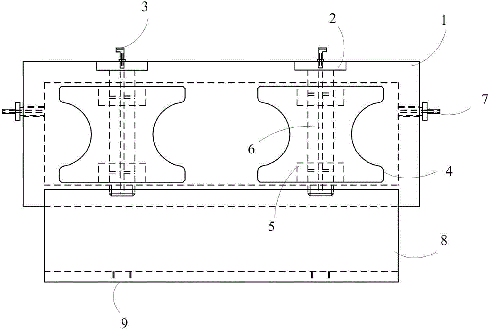
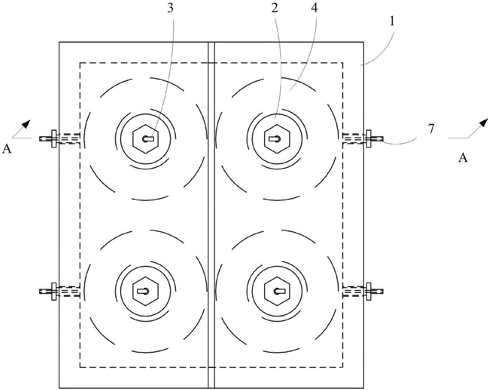
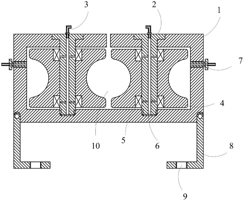
[0035] Such as Figure 1~3 As shown, the structure of the rolled piece rolling unit mechanism includes: a roller bracket 1, a pin shaft 2, an oil supply nozzle 3, a roller 4, a bearing 5, an oil supply channel 6, and a water supply nozzle 7. Wherein, the roller bracket 1 is a box structure, and a through groove is opened on the upper part, and pin shaft through holes are respectively arranged on both sides of the through slot; the bottom of the roller bracket 1, and the lower part of the pin shaft through hole are correspondingly provided with pin shaft fixing threads The bearing 5 is fixed on the...


PUM


Abstract

The invention discloses a rolled piece rolling unit mechanism. The rolled piece rolling unit mechanism comprises a roller support, a pin shaft, oil supply nozzles, rollers, a bearing, an oil supply passage and water supply nozzles; the roller support is a box body structure, a through groove is formed in the upper part of the roller support, and a pin shaft through hole is respectively formed in two sides of the through groove; a pin shaft fixed threaded counter bore is correspondently formed in the lower parts of the pin shaft through holes on the bottom of the roller support; the bearing is fixed on the pin shaft, the outer side of the bearing is fixed on an axial through hole of the roller, the end part of the pin shaft is provided with outer threads, the pin shaft penetrates through the pin shaft through hole and is fixed on the pin shaft fixed threaded counter bore by utilizing threads; the oil supply passage is arranged on the pin shaft, an opening is respectively formed in the positions, corresponding to the end part and the bearing fixing position of the pin shaft, of the oil supply passage, and the oil supply nozzle is arranged in the opening of the end part; a water supply threaded through hole is formed in the side wall of the roller support, and the water supply nozzle is arranged in the water supply threaded through hole; a rolling passage is formed between each pair of rollers at two sides of the through groove. The invention also discloses a rolling curve lead steel wire and an application method of the rolling curve lead steel wire.

Description

technical field [0001] The invention relates to a steel rolling technology, in particular to a rolled piece rolling unit mechanism, a rolling bend lead wire and a use method thereof. Background technique [0002] The large coil production line of our factory is one of the few coil lines in the country. Due to the "grafting" on the bar production line, affected by various factors such as technology and location, there An S-shaped curve. Due to the clamping of the 1# pinch roller of the large coil, there is a pulling force in the downstream direction of the rolled material, which in turn causes friction and sliding between the rolled piece and the lead steel pipe, resulting in scratches in the length direction of the rolled material. In this case, the S-shaped The curve performance is particularly outstanding, which has seriously restricted the improvement of the surface quality of our large coils. [0003] The prior art solution to this problem is as follows: [0004] 1. R...

Claims


Application Information

Patent Timeline
Patent Type & Authority Applications(China)
IPC IPC(8): B21B28/00
Inventor 郑启蒙
Owner INNER MONGOLIA BAOTOU STEEL UNION
Features
  • R&D
  • Intellectual Property
  • Life Sciences
  • Materials
  • Tech Scout
  • Unparalleled Data Quality
  • Higher Quality Content
  • 60% Fewer Hallucinations
Learn More