Supercharge Your Innovation With Domain-Expert AI Agents!

Accurate positioning device for corrugated pipe

A precise positioning and corrugated pipe technology, applied in the direction of bridge parts, structural elements, building components, etc., can solve the problems of reduced positioning qualification rate, prone to errors and errors, and reduced accuracy, and achieve efficient and smooth implementation, smooth pipelines, The effect of precise positioning

Inactive Publication Date: 2015-06-03
GANSU ROAD & BRIDGE CONSTR GROUP
View PDF6 Cites 4 Cited by
  • Summary
  • Abstract
  • Description
  • Claims
  • Application Information

AI Technical Summary

Problems solved by technology

[0004] However, since the installation of the corrugated pipe is not comprehensively considered in this platform, and the secondary installation of the corrugated pipe is carried out in a dense steel skeleton, the ordinary steel bar can only be cut off to avoid the corrugated pipe, so that the demolition and repair will make the It is more difficult to install, and it is difficult to ensure the smoothness of the bellows.
Moreover, on the base of the box girder to be prefabricated, it is necessary to use the traditional artificial inclined plane point-by-point distance positioning for the overall steel frame according to the single-piece method every time. In this way, mistakes and errors are easy to occur, which greatly reduces the accuracy. The deviation and yield of the bellows will greatly reduce the qualified rate of positioning, which is labor-intensive and time-consuming

Method used


Image

  • Accurate positioning device for corrugated pipe
  • Accurate positioning device for corrugated pipe
  • Accurate positioning device for corrugated pipe

Examples


Embodiment Construction

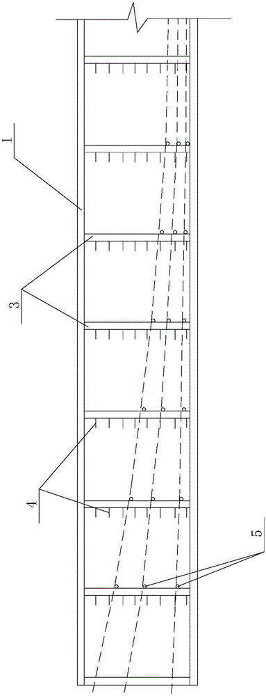
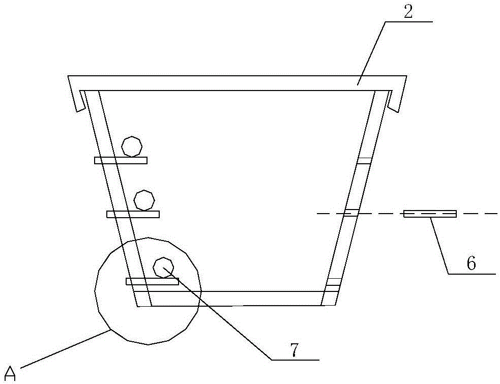
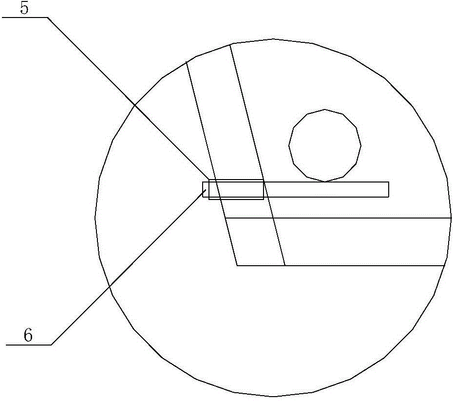
[0013] Such as Figure 1-3 As shown, this specific embodiment adopts the following technical solutions: it includes a box girder reinforcement platform formwork 1, a top locking rod 2, a vertical rod 3, a web distribution reinforcement positioning rib 4, a bellows positioning steel pipe 5 and a movable pin 6; Several top locking rods 2 are evenly arranged on the upper part of the box girder steel bar formwork 1, and several vertical bars 3 are evenly arranged on both sides of the box girder steel bar formwork 1, and several vertical bars 3 are evenly arranged on one side of each vertical bar 3. The web distributes reinforcing bar positioning ribs 4, and the other side of the vertical bar 3 is provided with several bellows positioning steel pipes 5, and the inside of the bellows positioning steel pipes 5 is plugged with movable pins 6, and the bellows 7 is placed on the movable pins 6.

[0014] This embodiment adopts the following fixing methods:

[0015] 1. Requirements for t...


PUM


Abstract

The invention discloses an accurate positioning device for a corrugated pipe and relates to the technical field of adopting pre-stress post-tensioning method for construction by a bridge engineering beam plate prefabricated member and a building type large-span prefabricated structure. The accurate positioning device comprises a box girder steel bar platform mold frame, top locking rods, vertical rods, web distributed steel bar positioning bars, corrugated pipe positioning steel pipes and movable pins, wherein the plurality of top locking rods are uniformly arranged at the upper part of the box girder steel bar platform mold frame in a transverse direction; the plurality of vertical rods are uniformly arranged on the two sides of the box girder steel bar platform mold frame; the plurality of web distributed steel bar positioning bars are uniformly arranged on one side of each vertical rod; the plurality of corrugated pipe positioning steel pipes are arranged on the other sides of the vertical rods; the movable pins are inserted into the corrugated pipe positioning steel pipes; and the corrugated pipe is arranged on the movable pins. By virtue of the accurate positioning device, theoretically calculated corrugated pipe subsection three-dimensional data can be efficiently and smoothly realized, accurate positioning can be performed, and a pipeline is smooth.

Description

Technical field: [0001] The invention relates to a bellows precise positioning device, which belongs to the technical field of prefabricated components of beams and slabs of bridge engineering and large-span prefabricated structures of buildings using prestressed post-tensioning method for construction. Background technique: [0002] In the construction of prefabricated girder and slab components of bridge engineering and large-span prefabricated structures (such as cover beams) using prestressed post-tensioning method, taking box girder as an example, the construction of box girder web and bottom plate steel skeleton is the most advanced method at present. It adopts a stereotyped platform (invention patent certificate No. 2914586; invention patent application number 201210507499.6; the patentee is Gansu Road and Bridge Construction Group Co., Ltd. The principle of the invention is: to make a table formwork with the same size as the steel skeleton, and a table formwork The l...

Claims


Application Information

Patent Timeline
Patent Type & Authority Applications(China)
IPC IPC(8): E04C5/18E04C5/10E01D19/00
Inventor 胡立志郑万鹏雒建奎王龙飞
Owner GANSU ROAD & BRIDGE CONSTR GROUP
Features
  • R&D
  • Intellectual Property
  • Life Sciences
  • Materials
  • Tech Scout
  • Unparalleled Data Quality
  • Higher Quality Content
  • 60% Fewer Hallucinations
Learn More